5 volt voltage stabilizer 7805. Simple linear current stabilizers for LEDs with your own hands
Currently, it is difficult to find any electronic device that does not use a stabilized power supply. Mainly as a power source, for the vast majority of various radio-electronic devices designed to operate from 5 volts, the best option would be to use a three-pin integrated 78L05.
Description of stabilizer 78L05
This stabilizer is inexpensive and easy to use, which makes it easier to design radio-electronic circuits with a significant number of printed circuit boards, to which an unstabilized DC voltage is supplied, and each board has its own stabilizer mounted separately.
The microcircuit - stabilizer 78L05 (7805) has thermal protection, as well as a built-in system that protects the stabilizer from overcurrent. However, for more reliable operation, it is advisable to use a diode to protect the stabilizer from a short circuit in the input circuit.
Technical parameters and pinout of stabilizer 78L05:
- Input voltage: 30 volts.
- Output voltage: 5.0 volts.
- Output current (maximum): 100 mA.
- Current consumption (stabilizer): 5.5 mA.
- Permissible input-output voltage difference: 1.7 volts.
- Operating temperature: -40 to +125 °C.


Multifunctional device for testing transistors, diodes, thyristors...
Analogs of stabilizer 78L05 (7805)
There are two types of this microcircuit: powerful 7805 (load current up to 1A) and low-power 78L05 (load current up to 0.1A). The foreign analogue of 7805 is ka7805. Domestic analogues for 78L05 are KR1157EN5, and for 7805 - 142EN5
Connection diagram 78L05
A typical connection circuit for the 78L05 stabilizer (according to the datasheet) is easy and does not require a large number of additional radio elements.

C1 at the input is necessary to eliminate RF interference when applying input voltage. Capacitor C2 at the output of the stabilizer, as in any other power source, ensures the stability of the power supply during sudden changes in load current, and also reduces the degree of ripple.
When designing a power supply, it is necessary to keep in mind that for stable operation of the 78L05 stabilizer, the input voltage must be at least 7 and no more than 20 volts.
Below are some examples of using the 78L05 Integrated Regulator.
Laboratory power supply for 78L05
This circuit is distinguished by its originality, due to the non-standard use of the microcircuit, the source of the reference voltage of which is the 78L05 stabilizer. Since the maximum permissible input voltage for the 78L05 is 20 volts, to prevent the 78L05 from failing, a parametric stabilizer was added to the circuit using the zener diode VD1 and resistor R1.

The TDA2030 chip is connected as a non-inverting amplifier. With this connection, the gain is 1+R4/R3 (in this case 6). Thus, the voltage at the output of the power supply, when the resistance of resistor R2 changes, will change from 0 to 30 volts (5 volts x 6). If you need to change the maximum output voltage, this can be done by selecting the appropriate resistance of resistor R3 or R4.

Kit for assembling an adjustable power supply...
Transformerless 5 volt power supply
this is characterized by increased stability, lack of heating of the elements and consists of accessible radio components.

The structure of the power supply includes: a power indicator on the HL1 LED, instead of a conventional transformer - a damping circuit on elements C1 and R2, a diode rectifier bridge VD1, capacitors to reduce ripple, a 9-volt zener diode VD2 and an integrated voltage regulator 78L05 (DA1). The need for a zener diode is due to the fact that the voltage from the output of the diode bridge is approximately 100 volts and this can damage the 78L05 stabilizer. You can use any zener diode with a stabilization voltage from 8...15 volts.
Attention!Since the circuit is not galvanically isolated from the mains, care should be taken when setting up and using the power supply.
Simple regulated power supply on the 78L05

The adjustable voltage range in this circuit is from 5 to 20 volts. The output voltage is changed using variable resistor R2. The maximum load current is 1.5 amperes. It is best to replace the 78L05 stabilizer with 7805 or its domestic analogue KR142EN5A. Transistor VT1 can be replaced with. It is advisable to place the powerful transistor VT2 on a radiator with an area of at least 150 square meters. cm.

Simple and intuitive operation, fast and accurate selection of voltage and current...
Universal charger circuit
This charger circuit is quite simple and universal. Charging allows you to charge all types of batteries: lithium, nickel, as well as small lead batteries used in uninterruptible power supplies.

It is known that when charging batteries, a stable charging current is important, which should be approximately 1/10 of the battery capacity. The constant charging current is ensured by the 78L05 (7805) stabilizer. The charger has 4 charging current ranges: 50, 100, 150 and 200 mA, which are determined by resistances R4…R7, respectively. Based on the fact that the output of the stabilizer is 5 volts, then to obtain, say, 50 mA, a 100 Ohm resistor is needed (5V / 0.05 A = 100) and so on for all ranges.
The circuit is also equipped with an indicator built on two transistors VT1, VT2 and an LED HL1. The LED goes off when the battery is charging.

charging current: 500 mA/h, 1000 mA/h. charging modes with constant...
Adjustable current source
Due to negative feedback through the load resistance, the voltage Uin is located at input 2 (inverting) of the TDA2030 (DA2) microcircuit. Under the influence of this voltage, a current flows through the load: Ih = Uin / R2. Based on this formula, the current flowing through the load does not depend on the resistance of this load.

Thus, by changing the voltage supplied from variable resistor R1 to input 1 of DA2 from 0 to 5 V, with a constant value of resistor R2 (10 Ohms), you can change the current flowing through the load in the range from 0 to 0.5 A.
A similar circuit can be successfully used as a charger for charging all kinds of batteries. The charging current is constant during the entire charging process and does not depend on the level of discharge of the battery or on the variability of the supply network. The charge current limit can be changed by decreasing or increasing the resistance of resistor R2.
(161.0 KiB, downloads: 6,505)
L7805-CV— for almost any radio amateur, assembling a power source with a stabilizing output voltage on the 7805 microcircuit and similar ones from this series is not difficult at all. It is this linear input DC voltage regulator that will be discussed in this material.
The figure above shows a typical linear circuit stabilizer L7805 with positive polarity 5v and rated operating current 1.5A. These microcircuits have become so famous that most of the world's companies have taken up their production. But in the picture below, the circuit is slightly improved, by increasing the capacitance of capacitors C1-C2.
As a rule, between radio engineers and electronics engineers this chip is called abbreviated, without naming the letters in front indicating the manufacturer. After all, it is already clear to everyone that this is a stabilizer, the last digit of which indicates its output voltage.
For those who have not yet encountered these electronic components in practice and know little about them, here is a short video on how to assemble the circuit for clarity:
Voltage stabilizer 5v! On the L7805CV chip
One of the important conditions is high quality components
In fact, when purchasing components, the manufacturer plays a significant role. When you purchase any electronic components, always pay attention to the brand of the part, and also ask who supplies it. Personally, I am satisfied with the products of STMicroelectronics, a manufacturer of microelectronic components.
Unnamed stabilizers or from little-known companies, as a rule, always cost less than similar ones from well-known brands. But the quality of such parts is not always at the proper level; their operation is especially affected by a significant variation in the output voltage.
Practically, I came across many times L7805 chips producing an output voltage within 4.6v, instead of 5v, while others from the same series gave, on the contrary, more - 5.3v. In addition, such samples can often create a decent background and increased power consumption.
Current source circuit made on microcircuits from the L78xx series
The value of the output current is determined by a constant resistor R* connected in parallel with a 0.1uF capacitor, it is this resistance that in turn creates a load for L7805. Moreover, the stabilizer does not have grounding. Only one output of the load resistance Rн goes to ground. The operating principle of such a switching circuit obliges the L7805-CV to supply a certain amount of current to the load by regulating the output voltage.
The magnitude of the current at the output of the source L78хх
An unpleasant moment that can be observed in the circuit is the summation of the quiescent current Id with the output current. The quiescent current parameters are indicated in the documentation for the microcircuit. Basically, such stabilizers have a constant quiescent current of 8 mA. This value is the smallest current of the chip's output circuit. Therefore, if you try to create a current source whose value is less than 8mA, it will not work.
Here you can download documentation for the L78xx chip
At best, you can get output currents ranging from 8mA to 1A from the L7805. However, when operating at currents exceeding 750-850 mA, we strongly recommend installing the microcircuit on a radiator. But working at such currents is still not justified. The current indicated in the documentation is 1A - this is its maximum value. In actual conditions, the chip will most likely fail due to overheating. Therefore, the optimal output operating current should be between 20 mA and 750 mA.
Correct output current and voltage value
At the same time, the non-constant quiescent current is formed as ΔId = 0.5 mA. This value indicates the correctness of the current setting in the output path. Accordingly, the accuracy of setting the output current depends on the load resistance of the microcircuit R*. In this case, it is desirable to use precision resistors with high stability and significant accuracy, from ±0.0005% to ±0.5%.
Optimal load resistance
At the same time, the value of the load resistance must be taken into account. Everything is simple here, that is, using Ohm's law you can calculate everything. For example:
V= I*R = 0.1 * 100 = 10 Volts
Based on these simple calculations, we found out what the voltage should be across a load with a resistance of 100 Ohms in order to create an output current of 100 mA. According to these calculations, it turns out that the best option would be to use a 7812 or 7815 microcircuit, designed for 12v and 15v, in order to have a reserve.
Conclusion
Naturally, in such a current source circuit there are limiting points. Although it can be useful for a large number of solutions in which high accuracy does not play a special role. The absence of any complexity in the circuit makes it possible to manufacture a current source in almost any conditions, especially since it is not difficult to purchase components for it.
Now let's talk about the three-pin L7805 stabilizer. The microcircuit is available in two types, in a plastic case - TO-220, for example, like the KT837 transistor, and in a metal case - TO-3, for example, like the well-known KT827. Three outputs, if you count from left to right, then respectively input, minus and output.
The last two digits in the marking indicate the stabilized output of the microcircuit - L7805 - 5 V, 7806 - 6 V.
Below is a description and connection diagram of the stabilizer, which is suitable for all microcircuits in this series.
We don’t look at small-capacity capacitors; it is advisable to install larger ones.

Output voltage - output voltage. Input voltage - input voltage. In our example, it gives us 5 volts at the output. Manufacturers noted that the desired input voltage is no more than 10 V. But it happens that the output stabilized voltage is sometimes either slightly underestimated or slightly overestimated. Here we see that the L7805 stabilizer can give us one of the voltages in the range 4.75 - 5.25 V, but the conditions must be met that the output current in the load will not exceed 1 ampere. Unstabilized DC voltage can be from 7.5 to 20 V, while the output will always be 5 V. This is a big plus of this radio component.
Pinout and dimensions of voltage stabilizer 7805 in a plastic case

Pinout and dimensions of voltage stabilizer 7805 in a metal case

For loads over 14 W, it is advisable to install the stabilizer on an aluminum heatsink; the greater the load, the greater the required cooling surface area.
Produced mainly in the TO-220 body
Maximum load current: 1.5A
Allowable input voltage: 35V
Output voltage: 5V
Number of regulators in the housing: 1
Current consumption: 6 mA
Accuracy: 4%
Operating temperature range: 0 C ... +140 C
Domestic analogue of KR142EN5A

In order to prevent the stabilizer from being completely damaged, you need to adhere to the required minimum at the input of the microcircuit, that is, if L7805, then we allow approximately 7-8 V to the input.
This is due to the fact that the stabilizer will dissipate excess power on itself. As you remember, the power formula is P=IU, where U is voltage and I is current. Consequently, the higher the input voltage of the stabilizer, the greater the power consumed by it. And excess power means overheating. As a result of heating, such a device may go into a protection state. Easy to use and the lack of setup and additional radio components has led to the fact that the stabilizer is well spread among radio amateurs, both beginners and professionals.
Positive voltage at 5V. Produced by STMircoelectronics, approximate price is about $1. Made in a standard TO-220 package (see figure), in which many transistors are made, however, its purpose is completely different.
In the marking of the 78XX series the last two digits indicate stabilized voltage rating, for example:
- 7805 - 5 V stabilization;
- 7812 - stabilization at 12 V;
- 7815 - stabilization at 15 V, etc.
The 79 series is designed for negative output voltage.
Is used for voltage stabilization in various low-voltage circuits. It is very convenient to use when it is necessary to ensure the accuracy of the supplied voltage; there is no need to install complex stabilization circuits, and all this can be replaced with one microcircuit and a couple of capacitors.
Connection diagram L7805CV
Connection diagram L 7805 CV It’s quite simple; to work, you need to place 0.33 µF capacitors at the input and 0.1 µF at the output according to the datasheet. It is important during installation or design to place the capacitors as close as possible to the terminals of the microcircuit. This is done to ensure the maximum level of stabilization and reduce interference.
By characteristics The L7805CV stabilizer is operational when an input DC voltage is supplied in the range from 7.5 to 25 V. The output of the microcircuit will have a stable DC voltage of 5 Volts. This is the beauty of the L7805CV chip.
Checking the functionality of the L7805CV
 How to check functionality microcircuits? To begin with, you can simply ring the terminals with a multimeter; if in at least one case a short is observed, then this clearly indicates a malfunction of the element. If you have a power source of 7 V or higher, you can assemble a circuit according to the datasheet given above and apply power to the input; at the output, use a multimeter to record the voltage at 5 V, so the element is absolutely operational. The third method is more labor-intensive if you do not have a power source. However, in this case, you will also receive a 5 V power supply in parallel. It is necessary to assemble a circuit with a rectifier bridge according to the figure presented below.
Needed for verification a step-down transformer with a transformation ratio of 18 - 20 and a rectifier bridge, a further standard kit, two capacitors for the stabilizer and that’s it, the 5 V power supply is ready. The capacitor values here are overestimated in relation to the L7805 connection diagram in the datasheet, this is due to the fact that it is better to smooth out voltage ripples after the rectifier bridge. For safer operation, it is advisable to add an indication to visualize the device being turned on. Then the diagram will look like this:
If there are a lot of capacitors or any other capacitive load on the load, you can protect the stabilizer with a reverse diode to prevent the element from burning out when the capacitors are discharged.
The big advantage of the microcircuit is Quite lightweight design and ease of use, if you need power of one value. Circuits sensitive to voltage values must be equipped with such stabilizers to protect elements sensitive to voltage surges.
Characteristics of the L7805CV stabilizer, its analogues
Main settings stabilizer L7805CV:
- Input voltage - from 7 to 25 V;
- Power dissipation - 15 W;
- Output voltage - 4.75…5.25 V;
- Output current - up to 1.5 A.
 Characteristics of the microcircuit shown in the table below, these values are valid subject to certain conditions. Namely, the temperature of the microcircuit is in the range from 0 to 125 degrees Celsius, the input voltage is 10 V, the output current is 500 mA (unless otherwise specified in the conditions, the Test conditions column), and the standard body kit with capacitors at the input is 0.33 μF and at the output 0 ,1 µF.
The table shows that the stabilizer behaves perfectly when powered at the input from 7 to 20 V and the output will stably output from 4.75 to 5.25 V. On the other hand, supplying higher values leads to a more significant spread of output values , therefore, above 25 V is not recommended, and a decrease in the input of less than 7 V will generally lead to the absence of voltage at the output of the stabilizer.
More than 5 W, it is necessary to install a radiator on the chip to avoid overheating of the stabilizer; the design allows this to be done without any questions. Naturally, such a stabilizer is not suitable for more precise (precision) equipment, because has a significant spread in the rated voltage when the input voltage changes.
Since the stabilizer is linear, it makes no sense to use it in powerful circuits; stabilization based on pulse-width modeling will be required, but for powering small devices As phones, children's toys, radio tape recorders and other gadgets, the L7805 is quite suitable. The domestic analogue is KR142EN5A or in common parlance “KRENKA”. In terms of cost, the analogue is also in the same category.
Stabilizers These are devices that are part of the power supply and allow you to maintain a stable voltage at the output of the power supply. Electrical voltage stabilizers are designed for some fixed output voltage (for example, 5V, 9V, 12V), and there are adjustable voltage stabilizers that have the ability to set the required voltage within the limits to which they allow.
All stabilizers are necessarily designed for a certain maximum current that they can provide. Exceeding this current threatens to damage the stabilizer. Modern stabilizers are necessarily equipped with current protection, which ensures that the stabilizer is turned off when the maximum current in the load is exceeded and overheating protection. Along with positive voltage stabilizers, there are negative voltage stabilizers. They are mainly used in bipolar power supplies.
7805 - stabilizer
7805 - stabilizer
This stabilizer has a low-power analogue.
7805 pinout
At the stabilizer 7805 pinout
In discussions of electrical circuits, the terms "voltage stabilizer" and "current stabilizer" are often used. But what's the difference between them? How do these stabilizers work? Which circuit requires an expensive voltage stabilizer, and where a simple regulator is enough? You will find answers to these questions in this article.
Let's look at a voltage stabilizer using the LM7805 device as an example. Its characteristics indicate: 5V 1.5A. This means it stabilizes the voltage and precisely up to 5V. 1.5A is the maximum current that the stabilizer can conduct. Peak current. That is, it can deliver 3 milliamps, 0.5 amperes, and 1 ampere. As much current as the load requires. But no more than one and a half. This is the main difference between a voltage stabilizer and a current stabilizer.
Types of voltage stabilizers
There are only 2 main types of voltage stabilizers:
- linear
- pulse
Linear voltage stabilizers
For example, microcircuits BANK or, LM1117, LM350.
By the way, KREN is not an abbreviation, as many people think. This is a reduction. A Soviet stabilizer chip similar to the LM7805 was designated KR142EN5A. Well, there is also KR1157EN12V, KR1157EN502, KR1157EN24A and a bunch of others. For brevity, the entire family of microcircuits began to be called “KREN”. KR142EN5A then turns into KREN142.
Soviet stabilizer KR142EN5A. Analogous to LM7805.

Stabilizer LM7805
The most common type. Their disadvantage is that they cannot operate at a voltage lower than the declared output voltage. If the voltage stabilizes at 5 volts, then it needs to be supplied at least one and a half volts more to the input. If we apply less than 6.5 V, then the output voltage will “sag” and we will no longer receive 5 V. Another disadvantage of linear stabilizers is strong heating under load. Actually, this is the principle of their operation - everything above the stabilized voltage simply turns into heat. If we supply 12 V to the input, then 7 V will be spent on heating the case, and 5 will go to the consumer. In this case, the case will heat up so much that without a heatsink the microcircuit will simply burn out. All this leads to another serious drawback - a linear stabilizer should not be used in battery-powered devices. The energy of the batteries will be spent on heating the stabilizer. Pulse stabilizers do not have all these disadvantages.
Switching voltage stabilizers
Switching stabilizers- do not have the disadvantages of linear ones, but are also more expensive. This is no longer just a chip with three pins. They look like a board with parts.

One of the options for the implementation of a pulse stabilizer.
Switching stabilizers There are three types: step-down, step-up and omnivorous. The most interesting ones are omnivores. Regardless of the input voltage, the output will be exactly what we need. An omnivorous pulse generator doesn’t care if the input voltage is lower or higher than required. It automatically switches to the mode of increasing or decreasing the voltage and maintains the set output. If the specifications state that the stabilizer can be supplied with 1 to 15 volts at the input and the output will be stable at 5, then it will be so. In addition, heating pulse stabilizers so insignificant that in most cases it can be neglected. If your circuit will be powered by batteries or placed in a closed case, where strong heating of the linear stabilizer is unacceptable, use a pulsed one. I use custom switching voltage stabilizers for pennies, which I order from Aliexpress. You can buy it.
Fine. What about the current stabilizer?
I won't discover America if I say that current stabilizer stabilizes the current.
Current stabilizers are also sometimes called LED driver. Externally, they are similar to pulse voltage stabilizers. Although the stabilizer itself is a small microcircuit, everything else is needed to ensure the correct operating mode. But usually the entire circuit is called a driver at once.

This is what a current stabilizer looks like. Circled in red is the same circuit that is the stabilizer. Everything else on the board is wiring.
So. The driver sets the current. Stable! If it is written that the output current will be 350mA, then it will be exactly 350mA. But the output voltage may vary depending on the voltage required by the consumer. Let's not get into the wilds of theories about that. how it all works. Let's just remember that you don't regulate the voltage, the driver will do everything for you based on the consumer.
Well, why is all this necessary?
Now you know how a voltage stabilizer differs from a current stabilizer and you can navigate their diversity. Perhaps you still don’t understand why these things are needed.
Example: you want to power 3 LEDs from the car's on-board power supply. As you can learn from, for an LED it is important to control the current strength. We use the most common option for connecting LEDs: 3 LEDs and a resistor are connected in series. Supply voltage - 12 volts.
We limit the current to the LEDs with a resistor so that they do not burn out. Let the voltage drop across the LED be 3.4 volts.
After the first LED, 12-3.4 = 8.6 volts remains.
We have enough for now.
On the second, another 3.4 volts will be lost, that is, 8.6-3.4 = 5.2 volts will remain.
And there will be enough for the third LED too.
And after the third there will be 5.2-3.4 = 1.8 volts.
If you want to add a fourth LED, it won't be enough.
If the supply voltage is raised to 15V, then it will be enough. But then the resistor will also need to be recalculated. A resistor is the simplest current stabilizer (limiter). They are often placed on the same tapes and modules. It has a minus - the lower the voltage, the less current on the LED will be (Ohm’s law, you can’t argue with it). This means that if the input voltage is unstable (this is usually the case in cars), then you first need to stabilize the voltage, and then you can limit the current with a resistor to the required values. If we use a resistor as a current limiter where the voltage is not stable, we need to stabilize the voltage.
It is worth remembering that it makes sense to install resistors only up to a certain current strength. After a certain threshold, the resistors begin to get very hot and you have to install more powerful resistors (why a resistor needs power is described in the article about this device). Heat generation increases, efficiency decreases.
Also called an LED driver. Often, those who are not well versed in this, a voltage stabilizer is simply called an LED driver, and a pulse current stabilizer is called good LED driver. It immediately produces stable voltage and current. And it hardly gets hot. This is what it looks like:

Integrated voltage stabilizers, and especially one type of them - stabilizers with a fixed output voltage in three-terminal packages, have found wide application in electronics. They are good because they do not require external elements (except for filter capacitors), adjustments and have a wide range of load currents. I will not give their technical characteristics here, but will provide only basic data and diagrams of possible applications.
Standard linear stabilizers are produced by many manufacturers and have more than one designation; we will look at them using the example of the most typical type:
- L78 series ( for positive voltages),
- and L79 series ( for negative voltages).
In turn, standard regulators are divided into:
- low-current with an output current in the region of 0.1 A (L78Lхх) - view in fig. 1a,
- with an average current value of about 0.5 A (L78Мхх) - view in Fig. 1b,
- high-current 1...1.5 A (L78хх) - view in --Fig. 1c.
Low cost, ease of use, and a wide variety of output voltages and packages make these components very popular when creating simple power supply circuits. It should be noted that these regulators have a number of additional functions that ensure safe operation. These include overcurrent protection and temperature protection against overheating of the chip.
Picture 1
Integral stabilizers use housing types: KT-26, KT-27, KT-28-2, TO-220,
KT-28-2, KT-27-2, TO-92, TO-126, TO-202, which are close to those shown in Fig. 1.
78xx series chips
This is the 78xx series of linear regulator ICs with a fixed output voltage (also known as LM78xx).
Their popularity is due, as mentioned above, to their ease of use and relative cheapness. When specifying certain microcircuits of the series, “xx” is replaced with a two-digit number indicating the output voltage of the stabilizer (for example, the 7805 microcircuit has an output voltage of 5 volts, and 7812 - 12V). Stabilizers of the 78th series have a positive operating voltage relative to ground, and the 79xx series is negative and has a similar designation system. They can be used to provide both positive and negative supply voltages to loads in the same circuit.
In addition, their series popularity is dictated by several advantages over other voltage stabilizers:
- The series microcircuits do not require additional elements to ensure stable power supply, which makes them easy to use, economical and efficient in using space on the printed circuit board. In contrast, most other stabilizers require additional components either to set the desired voltage value or to assist in stabilization. Some other options (for example, switching regulators) not only require a large number of additional components, but may require a lot of development experience.
- The series devices are protected against exceeding the maximum current, as well as against overheating and short circuits, which ensures high reliability in most cases. Sometimes current limiting is also used to protect other circuit components.
- Linear stabilizers do not create RF interference in the form of magnetic stray fields and RF output voltage pulsations.
The disadvantages of linear stabilizers include lower efficiency compared to pulse ones, but with optimal calculation it can exceed 60%.
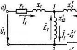
The structure of the integral stabilizer is shown in Fig. 2

Figure 2
Requirements for the use of stabilizers:
The voltage drop across it should not be lower than 2 volts,
the maximum current through it should not exceed that specified in the ratio:
I max P is the permissible power dissipation of the microcircuit, U in-out is the voltage drop across the microcircuit (U in-out = U in - U out). A typical circuit diagram for connecting an integrated voltage stabilizer in a three-terminal package with a fixed output voltage is shown in Fig. 3. Figure 3 We see that microcircuits of this type do not require additional elements other than voltage-filtering capacitors - which filter the supply voltage and protect the stabilizer from interference coming from the load and from the supply voltage source. To ensure stable operation of the 78xx series microcircuits over the entire range of permissible values of input and output voltages and load currents, it is recommended to use capacitors that shunt the input and output of the stabilizer. These should be solid-state (ceramic or tantalum) capacitors with a capacity of up to 2 µF at the input and 1 µF at the output. When using aluminum capacitors, their capacitance must be more than 10 microfarads. It is necessary to connect capacitors with as short conductors as possible and as close as possible to the stabilizer terminals.Typical circuit diagram for connecting a voltage stabilizer in a technical output housing
with fixed output voltage
Application options for an integrated stabilizer with a fixed voltage
Microcircuits allow you to create many circuits based on stabilizers.
Output voltage adjustment
As I wrote above (see Fig. 5b), linear stabilizers allow you to change the output voltage. shown in Fig. 7.
Using the same scheme, functional regulation of the output voltage is also possible.
For example, it is possible to regulate the output voltage depending on temperature for use in temperature stabilization systems - thermostats. Depending on the type of temperature sensor, it may be switched on instead of resistors R 1 or R 2.

Figure 7
Parallel connection of stabilizers
Figure 7
This regulator has the peculiarity that (for stable fan rotation) at the initial moment of time, full voltage (12V) is supplied to the fan. After capacitor C1 is charged, the output voltage will be determined by resistor R2.
Stabilizer with smooth output

Figure 8
This circuit differs in that at the initial moment of time the voltage at the output of the stabilizer is 5V (for this type), after which the voltage smoothly rises to a value determined by the control elements.
Collected by A. Sorokin,
Options:
Min. input voltage, V:
Max. input voltage, V: 35
Output voltage, V: +5
Rated output current, A: 1.5
Voltage drop in/out, V: 2.5
Number of regulators in the housing: 1
Current consumption, mA: 6
Accuracy: 4%
Operating temperature range: 0°C … +150°C
These are devices that are part of the power supply and allow you to maintain a stable voltage at the output of the power supply. Electrical voltage stabilizers are designed for some fixed output voltage (for example, 5V, 9V, 12V), and there are adjustable voltage stabilizers that have the ability to set the required voltage within the limits to which they allow.
All stabilizers are necessarily designed for a certain maximum current that they can provide. Exceeding this current threatens to damage the stabilizer. Modern stabilizers are necessarily equipped with current protection, which ensures that the stabilizer is turned off when the maximum current in the load is exceeded and overheating protection. Along with positive voltage stabilizers, there are negative voltage stabilizers. They are mainly used in bipolar power supplies.


7805 - stabilizer, made in a housing similar to a transistor and has three terminals. See picture. (+5V stabilized voltage and current 1A). There is also a hole in the case for attaching the voltage stabilizer 7805 to the cooling radiator. The 7805 is a positive voltage regulator. Its mirror image - 7905 - analogue 7805 for negative voltage. Those. it will have + at the common output, and - will be supplied to the input. Accordingly, a stabilized voltage of -5 volts will be removed from its output.
It is also worth noting that for normal operation, a voltage of about 10 volts must be supplied to the input of both stabilizers.
This stabilizer has a low-power analogue 78L05.
7805 pinout
At the stabilizer pinout next. If you look at the 7805 case as shown in the photo above, the pins have the following pinout from left to right: input, common, output. The “common” terminal has a contact to the housing. This must be taken into account during installation. Stabilizer 7905 has a different pinout! From left to right: general, entrance, exit. And it has an “entrance” on its body!

Almost all amateur radio homemade products and designs include a stabilized power source. And if your circuit operates on a supply voltage of 5 volts, then the best option would be to use a three-terminal integrated stabilizer 78L05
In nature, there are two varieties of 7805 with a load current of up to 1A and the lower-power 78L05 with a load current of up to 0.1A. In addition, an intermediate option is the 78M05 microcircuit with a load current of up to 0.5A. Complete domestic analogues of the microcircuit are for 78L05 KR1157EN5 and 7805 for 142EN5

Capacitance C1 at the input is required to cut off high-frequency interference when applying input voltage. Capacitance C2, but already at the output of the stabilizer, sets the voltage stability during a sharp change in the load current, and also significantly reduces the degree of ripple.
When designing, you need to remember that for normal operation of the 78L05 stabilizer, the input voltage must be no lower than 7 and no higher than 20 volts.
The control circuit allows you to supply and disable power going to the voltage stabilizer. The control signal must be TTL or CMOS level. The circuit can be used as a power switch controlled by a microcontroller.

Below we will consider a selection of the most interesting examples of the practical use of the 78L05 integrated stabilizer.
This design of the laboratory power supply is distinguished by its sophistication, primarily due to the non-standard use of the TDA2030 microcircuit, the source of which is stabilized voltage is 78L05.

The TDA2030 is included as a non-inverting amplifier. With this connection, the gain is calculated by the formula 1 + R4/R3 and is equal to 6. Therefore, the voltage at the output of the power supply, when adjusting the resistance value R2, will smoothly change from 0 to 30 volts.
Increased stability and no overheating of radio components are the main advantages of this design.

The power-on indicator is made on the HL1 LED; instead of a transformer, a damping circuit is used on components C1 and R1, a diode rectifier bridge on a specialized assembly, capacitors are used to minimize ripple, a 9-volt zener diode and a 78L05 voltage stabilizer. The need to use a zener diode is determined by the fact that the voltage from the output of the diode bridge is about 100 volts and this can damage the 78L05 stabilizer.

The voltage range in this circuit is from 5 to 20 volts. The output voltage is changed by variable resistance R2. The maximum load current is about 1.5 amperes.
The device is capable of charging different types of batteries: lithium, nickel, as well as lead batteries used in uninterruptible power supplies.

When charging batteries, you need a stable charging current, which should be about 1/10 of the battery capacity. The constancy of the charging current is set by the stabilizer 78L05. The charger has four charging current ranges: 50.5 volts, then to obtain a current of 50 mA a resistance of 100 ohms is required based on Ohm's law. For convenience, the design of the charger has an indicator made of two bipolar transistors and an LED. The LED goes out when the battery is charging.