Homemade television antenna: for DVB and analog signal - theory, types, manufacturing. Parting with a zigzag, technique of creation and hairstyles for it Video: example of a double triangular antenna
Once upon a time, a good television antenna was in short supply; purchased ones did not differ in quality and durability, to put it mildly. Making an antenna for a “box” or “coffin” (an old tube TV) with your own hands was considered a sign of skill. Interest in homemade antennas continues to this day. There is nothing strange here: the conditions for TV reception have changed dramatically, and manufacturers, believing that there is and will not be anything significantly new in the theory of antennas, most often adapt electronics to long-known designs, without thinking about the fact that The main thing for any antenna is its interaction with the signal on the air.
What has changed on air?
Firstly, almost the entire volume of TV broadcasting is currently carried out in the UHF range. First of all, for economic reasons, it greatly simplifies and reduces the cost of the antenna-feeder system of transmitting stations, and, more importantly, the need for its regular maintenance by highly qualified specialists engaged in hard, harmful and dangerous work.
Second - TV transmitters now cover almost all more or less populated areas with their signal, and a developed communication network ensures the delivery of programs to the most remote corners. There, broadcasting in the habitable zone is provided by low-power, unattended transmitters.
Third, the conditions for the propagation of radio waves in cities have changed. On the UHF, industrial interference leaks in weakly, but reinforced concrete high-rise buildings are good mirrors for them, repeatedly reflecting the signal until it is completely attenuated in an area of seemingly reliable reception.
Fourth - There are a lot of TV programs on air now, dozens and hundreds. How diverse and meaningful this set is is another question, but counting on receiving 1-2-3 channels is now pointless.
Finally, digital broadcasting has developed. The DVB T2 signal is a special thing. Where it still exceeds the noise even just a little, by 1.5-2 dB, the reception is excellent, as if nothing had happened. But a little further or to the side - no, it’s cut off. Digital is almost insensitive to interference, but if there is a mismatch with the cable or phase distortion anywhere in the path, from the camera to the tuner, the picture can crumble into squares even with a strong clean signal.
Antenna requirements
In accordance with the new reception conditions, the basic requirements for TV antennas have also changed:
- Its parameters such as the directivity coefficient (DAC) and the protective action coefficient (PAC) are now of no decisive importance: modern air is very dirty, and along the tiny side lobe of the directional pattern (DP), at least some interference will get through, and You need to fight it using electronic means.
- In return, the antenna's own gain (GA) becomes especially important. An antenna that “catches” the air well, rather than looking at it through a small hole, will provide a reserve of power for the received signal, allowing the electronics to clear it of noise and interference.
- A modern television antenna, with rare exceptions, must be a range antenna, i.e. its electrical parameters must be preserved naturally, at the level of theory, and not squeezed into acceptable limits through engineering tricks.
- The TV antenna must be matched with the cable over its entire operating frequency range without additional matching and balancing devices (MCD).
- The amplitude-frequency response of the antenna (AFC) should be as smooth as possible. Sharp surges and dips are certainly accompanied by phase distortions.
The last 3 points are determined by the requirements for receiving digital signals. Customized, i.e. Working theoretically at the same frequency, antennas can be “stretched” in frequency, for example. antennas of the “wave channel” type on the UHF with an acceptable signal-to-noise ratio capture channels 21-40. But their coordination with the feeder requires the use of USSs, which either strongly absorb the signal (ferrite) or spoil the phase response at the edges of the range (tuned). And such an antenna, which works perfectly on analogue, will receive “digital” poorly.
In this regard, from all the great variety of antennas, this article will consider TV antennas, available for self-production, of the following types:
- Frequency independent (all-wave)– does not have high parameters, but is very simple and cheap, it can be done in literally an hour. Outside the city, where the airwaves are cleaner, it will be able to receive digital or a fairly powerful analogue not a short distance from the television center.
- Range log-periodic. Figuratively speaking, it can be likened to a fishing trawl, which sorts the prey during fishing. It is also quite simple, fits perfectly with the feeder throughout its entire range, and does not change its parameters at all. The technical parameters are average, so it is more suitable for a summer residence, and in the city as a room.
- Several modifications of the zigzag antenna, or Z-antennas. In the MV range, this is a very solid design that requires considerable skill and time. But on the UHF, due to the principle of geometric similarity (see below), it is so simplified and shrunk that it can well be used as a highly efficient indoor antenna under almost any reception conditions.
Note: The Z-antenna, to use the previous analogy, is a frequent flyer that scoops up everything in the water. As the air became littered, it fell out of use, but with the development of digital TV, it was once again on the high horse - throughout its entire range, it is just as perfectly coordinated and keeps the parameters as a “speech therapist.”
Precise matching and balancing of almost all antennas described below is achieved by laying the cable through the so-called. zero potential point. It has special requirements, which will be discussed in more detail below.
About vibrator antennas
In the frequency band of one analog channel, up to several dozen digital ones can be transmitted. And, as already said, the digital works with an insignificant signal-to-noise ratio. Therefore, in places very remote from the television center, where the signal of one or two channels barely reaches, the good old wave channel (AVK, wave channel antenna), from the class of vibrator antennas, can be used for receiving digital TV, so at the end we will devote a few lines and to her.
About satellite reception
There is no point in making a satellite dish yourself. You still need to buy a head and a tuner, and behind the external simplicity of the mirror lies a parabolic surface of oblique incidence, which not every industrial enterprise can produce with the required accuracy. The only thing homemade people can do is set up a satellite dish, about that.
About antenna parameters
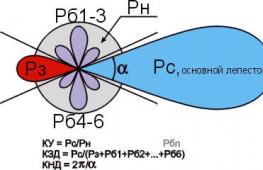
Accurate determination of the antenna parameters mentioned above requires knowledge of higher mathematics and electrodynamics, but it is necessary to understand their meaning when starting to manufacture an antenna. Therefore, we will give somewhat rough, but still clarifying definitions (see figure on the right):

- KU is the ratio of the signal power received by the antenna on the main (main) lobe of its DP to its same power received in the same place and at the same frequency by an omnidirectional, circular, DP antenna.
- KND is the ratio of the solid angle of the entire sphere to the solid angle of the opening of the main lobe of the DN, assuming that its cross section is a circle. If the main petal has different sizes in different planes, you need to compare the area of the sphere and its cross-sectional area of the main petal.
- SCR is the ratio of the signal power received at the main lobe to the sum of the interference powers at the same frequency received by all secondary (back and side) lobes.
Notes:
- If the antenna is a band antenna, the powers are calculated at the frequency of the useful signal.
- Since there are no completely omnidirectional antennas, a half-wave linear dipole oriented in the direction of the electric field vector (according to its polarization) is taken as such. Its QU is considered equal to 1. TV programs are transmitted with horizontal polarization.
It should be remembered that CG and KNI are not necessarily interrelated. There are antennas (for example, “spy” - single-wire traveling wave antenna, ABC) with high directivity, but single or lower gain. These look into the distance as if through a diopter sight. On the other hand, there are antennas, e.g. Z-antenna, which combines low directivity with significant gain.
About the intricacies of manufacturing
All antenna elements through which useful signal currents flow (specifically, in the descriptions of individual antennas) must be connected to each other by soldering or welding. In any prefabricated unit in the open air, the electrical contact will soon be broken, and the parameters of the antenna will deteriorate sharply, up to its complete unusability.
This is especially true for points of zero potential. In them, as experts say, there is a voltage node and a current antinode, i.e. its greatest value. Current at zero voltage? Nothing surprising. Electrodynamics has moved as far from Ohm's law on direct current as the T-50 has gone from a kite.
Places with zero potential points for digital antennas are best made bent from solid metal. A small “creeping” current in welding when receiving the analogue in the picture will most likely not affect it. But, if a digital signal is received at the noise level, then the tuner may not see the signal due to the “creep”. Which, with pure current at the antinode, would give stable reception.
About cable soldering
The braid (and often the central core) of modern coaxial cables is made not of copper, but of corrosion-resistant and inexpensive alloys. They solder poorly and if you heat them for a long time, you can burn out the cable. Therefore, you need to solder the cables with a 40-W soldering iron, low-melting solder and with flux paste instead of rosin or alcohol rosin. There is no need to spare the paste; the solder immediately spreads along the veins of the braid only under a layer of boiling flux.

Types of antennas
All-wave
An all-wave (more precisely, frequency-independent, FNA) antenna is shown in Fig. It consists of two triangular metal plates, two wooden slats, and a lot of enameled copper wires. The diameter of the wire does not matter, and the distance between the ends of the wires on the slats is 20-30 mm. The gap between the plates to which the other ends of the wires are soldered is 10 mm.
Note: Instead of two metal plates, it is better to take a square of one-sided foil fiberglass with triangles cut out of copper.
The width of the antenna is equal to its height, the opening angle of the blades is 90 degrees. The cable routing diagram is shown there in Fig. The point marked in yellow is the point of quasi-zero potential. There is no need to solder the cable braid to the fabric in it, just tie it tightly, and the capacity between the braid and the fabric will be enough for matching.
The CHNA, stretched in a window 1.5 m wide, receives all meter and DCM channels from almost all directions, except for a dip of about 15 degrees in the plane of the canvas. This is its advantage in places where it is possible to receive signals from different television centers; it does not need to be rotated. Disadvantages - single gain and zero gain, therefore, in the interference zone and outside the zone of reliable reception, the CNA is not suitable.
Note : There are other types of CNA, for example. in the form of a two-turn logarithmic spiral. It is more compact than the CNA made of triangular sheets in the same frequency range, therefore it is sometimes used in technology. But in everyday life this does not provide any advantages, it is more difficult to make a spiral CNA, and it is more difficult to coordinate with a coaxial cable, so we are not considering it.
Based on the CHNA, the once very popular fan vibrator (horns, flyer, slingshot) was created, see fig. Its directivity factor and coefficient of performance are something around 1.4 with a fairly smooth frequency response and linear phase response, so it would be suitable for digital use even now. But - it works only on HF (channels 1-12), and digital broadcasting is on UHF. However, in the countryside, with an elevation of 10-12 m, it may be suitable for receiving an analogue. Mast 2 can be made of any material, but fastening strips 1 are made of a good non-wetting dielectric: fiberglass or fluoroplastic with a thickness of at least 10 mm.

Beer all-wave

The all-wave antenna made from beer cans is clearly not the fruit of the hangover hallucinations of a drunken radio amateur. This is truly a very good antenna for all reception situations, you just need to do it right. And it’s extremely simple.
Its design is based on the following phenomenon: if you increase the diameter of the arms of a conventional linear vibrator, then its operating frequency band expands, but other parameters remain unchanged. In long-distance radio communications, since the 20s, the so-called Nadenenko's dipole based on this principle. And beer cans are just the right size to serve as the arms of a vibrator on the UHF. In essence, the CHNA is a dipole, the arms of which expand indefinitely to infinity.
The simplest beer vibrator made of two cans is suitable for indoor analogue reception in the city, even without coordination with the cable, if its length is no more than 2 m, on the left in Fig. And if you assemble a vertical in-phase array from beer dipoles with a step of half a wave (on the right in the figure), match it and balance it using an amplifier from a Polish antenna (we will talk about it later), then thanks to the vertical compression of the main lobe of the pattern, such an antenna will give good CU.
The gain of the “tavern” can be further increased by adding a CPD at the same time, if a mesh screen is placed behind it at a distance equal to half the grid pitch. The beer grill is mounted on a dielectric mast; The mechanical connections between the screen and the mast are also dielectric. The rest is clear from the following. rice.

Note: the optimal number of lattice floors is 3-4. With 2, the gain in gain will be small, and more is difficult to coordinate with the cable.
Video: making a simple antenna from beer cans
"Speech therapist"
A log-periodic antenna (LPA) is a collecting line to which halves of linear dipoles (i.e., pieces of conductor a quarter of the operating wavelength) are alternately connected, the length and distance between which vary in geometric progression with an index less than 1, in the center in Fig. The line can be either configured (with a short circuit at the end opposite to the cable connection) or free. An LPA on a free (unconfigured) line is preferable for digital reception: it comes out longer, but its frequency response and phase response are smooth, and the matching with the cable does not depend on frequency, so we will focus on it.

The LPA can be manufactured for any predetermined frequency range, up to 1-2 GHz. When the operating frequency changes, its active region of 1-5 dipoles moves back and forth along the canvas. Therefore, the closer the progression indicator is to 1, and accordingly the smaller the antenna opening angle, the greater the gain it will give, but at the same time its length increases. At UHF, 26 dB can be achieved from an outdoor LPA, and 12 dB from a room LPA.
LPA can be said to be an ideal digital antenna based on its totality of qualities, so let’s look at its calculation in a little more detail. The main thing you need to know is that an increase in the progression indicator (tau in the figure) gives an increase in gain, and a decrease in the LPA opening angle (alpha) increases the directivity. A screen is not needed for the LPA; it has almost no effect on its parameters.
Calculation of digital LPA has the following features:
- They start it, for the sake of frequency reserve, with the second longest vibrator.
- Then, taking the reciprocal of the progression index, the longest dipole is calculated.
- After the shortest dipole based on the given frequency range, another one is added.
Let's explain with an example. Let's say our digital programs are in the range of 21-31 TVK, i.e. at 470-558 MHz in frequency; wavelengths, respectively, are 638-537 mm. Let’s also assume that we need to receive a weak noisy signal far from the station, so we take the maximum (0.9) progression rate and the minimum (30 degrees) opening angle. For the calculation, you will need half the opening angle, i.e. 15 degrees in our case. The opening can be further reduced, but the length of the antenna will increase exorbitantly, in cotangent terms.
We consider B2 in Fig: 638/2 = 319 mm, and the arms of the dipole will be 160 mm each, you can round up to 1 mm. The calculation will need to be carried out until you get Bn = 537/2 = 269 mm, and then calculate another dipole.
Now we consider A2 as B2/tg15 = 319/0.26795 = 1190 mm. Then, through the progression indicator, A1 and B1: A1 = A2/0.9 = 1322 mm; B1 = 319/0.9 = 354.5 = 355 mm. Next, sequentially, starting with B2 and A2, we multiply by the indicator until we reach 269 mm:
- B3 = B2*0.9 = 287 mm; A3 = A2*0.9 = 1071 mm.
- B4 = 258 mm; A4 = 964 mm.
Stop, we are already less than 269 mm. We check whether we can meet the gain requirements, although it is clear that we can’t: to get 12 dB or more, the distances between the dipoles should not exceed 0.1-0.12 wavelengths. In this case, for B1 we have A1-A2 = 1322 – 1190 = 132 mm, which is 132/638 = 0.21 wavelengths of B1. We need to “pull up” the indicator to 1, to 0.93-0.97, so we try different ones until the first difference A1-A2 is reduced by half or more. For a maximum of 26 dB, you need a distance between dipoles of 0.03-0.05 wavelengths, but not less than 2 dipole diameters, 3-10 mm at UHF.
Note: cut off the rest of the line behind the shortest dipole; it is needed only for calculations. Therefore, the actual length of the finished antenna will be only about 400 mm. If our LPA is external, this is very good: we can reduce the opening, obtaining greater directionality and protection from interference.
Video: antenna for digital TV DVB T2
About the line and the mast
The diameter of the tubes of the LPA line on the UHF is 8-15 mm; the distance between their axes is 3-4 diameters. Let’s also take into account that thin “lace” cables give such attenuation per meter on the UHF that all antenna-amplification tricks will come to naught. You need to take a good coaxial for an outdoor antenna, with a shell diameter of 6-8 mm. That is, the tubes for the line must be thin-walled, seamless. You cannot tie the cable to the line from the outside; the quality of the LPA will drop sharply.
It is necessary, of course, to attach the outer propulsion boat to the mast by the center of gravity, otherwise the small windage of the propulsion craft will turn into a huge and shaking one. But it is also impossible to connect a metal mast directly to the line: you need to provide a dielectric insert of at least 1.5 m in length. The quality of the dielectric does not play a big role here; oiled and painted wood will do.
About the Delta antenna
If the UHF LPA is consistent with the cable amplifier (see below, about Polish antennas), then the arms of a meter dipole, linear or fan-shaped, like a “slingshot”, can be attached to the line. Then we will get a universal VHF-UHF antenna of excellent quality. This solution is used in the popular Delta antenna, see fig.

Antenna “Delta”
Zigzag on air
A Z-antenna with a reflector gives the same gain and gain as the LPA, but its main lobe is more than twice as wide horizontally. This can be important in rural areas when there is TV reception from different directions. And the decimeter Z-antenna has small dimensions, which is essential for indoor reception. But its operating range is theoretically not unlimited; frequency overlap while maintaining parameters acceptable for the digital range is up to 2.7.

The design of the MV Z-antenna is shown in Fig; The cable route is highlighted in red. There in the lower left there is a more compact ring version, colloquially known as a “spider”. It clearly shows that the Z-antenna was born as a combination of a CNA with a range vibrator; There is also something of a rhombic antenna in it, which does not fit into the theme. Yes, the “spider” ring does not have to be wooden, it can be a metal hoop. "Spider" receives 1-12 MV channels; The pattern without a reflector is almost circular.
The classic zigzag works either on 1-5 or 6-12 channels, but for its manufacture you only need wooden slats, enameled copper wire with d = 0.6-1.2 mm and several scraps of foil fiberglass, so we give the dimensions in fraction for 1-5/6-12 channels: A = 3400/950 mm, B, C = 1700/450 mm, b = 100/28 mm, B = 300/100 mm. At point E there is zero potential; here you need to solder the braid to a metallized support plate. Reflector dimensions, also 1-5/6-12: A = 620/175 mm, B = 300/130 mm, D = 3200/900 mm.
The range Z-antenna with a reflector gives a gain of 12 dB, tuned to one channel - 26 dB. To build a single-channel one based on a band zigzag, you need to take the side of the square of the canvas in the middle of its width at a quarter of the wavelength and recalculate all other dimensions proportionally.
Folk Zigzag
As you can see, the MV Z-antenna is a rather complex structure. But its principle shows itself in all its glory on the UHF. The UHF Z-antenna with capacitive inserts, combining the advantages of the “classics” and the “spider”, is so easy to make that even in the USSR it earned the title of folk antenna, see fig.

Material – copper tube or aluminum sheet with a thickness of 6 mm. The side squares are solid metal or covered with mesh, or covered with a tin. In the last two cases, they need to be soldered along the circuit. The coax cannot be bent sharply, so we guide it so that it reaches the side corner, and then does not go beyond the capacitive insert (side square). At point A (zero potential point), we electrically connect the cable braid to the fabric.
Note: aluminum cannot be soldered with conventional solders and fluxes, so “folk” aluminum is suitable for outdoor installation only after sealing the electrical connections with silicone, since everything in it is screwed.
Video: example of a double triangle antenna
Wave channel

The wave channel antenna (AWC), or Udo-Yagi antenna, available for self-production, is capable of giving the highest gain, directivity factor and efficiency factor. But it can only receive digital signals on UHF on 1 or 2-3 adjacent channels, because belongs to the class of highly tuned antennas. Its parameters deteriorate sharply beyond the tuning frequency. It is recommended to use AVK under very poor reception conditions, and make a separate one for each TVK. Fortunately, this is not very difficult - AVK is simple and cheap.
The operation of the AVK is based on “raking” the electromagnetic field (EMF) of the signal to the active vibrator. Externally small, lightweight, with minimal windage, the AVK can have an effective aperture of dozens of wavelengths of the operating frequency. Directors (directors) that are shortened and therefore have capacitive impedance (impedance) direct the EMF to the active vibrator, and the reflector (reflector), elongated, with inductive impedance, throws back to it what has slipped past. Only 1 reflector is needed in an AVK, but there can be from 1 to 20 or more directors. The more there are, the higher the gain of the AVC, but the narrower its frequency band.
From interaction with the reflector and directors, the wave impedance of the active (from which the signal is taken) vibrator drops the more, the closer the antenna is tuned to the maximum gain, and coordination with the cable is lost. Therefore, the active dipole AVK is made into a loop, its initial wave impedance is not 73 Ohms, like a linear one, but 300 Ohms. At the cost of reducing it to 75 Ohms, an AVK with three directors (five-element, see the figure on the right) can be adjusted to almost a maximum gain of 26 dB. A characteristic pattern for AVK in the horizontal plane is shown in Fig. at the beginning of the article.
AVK elements are connected to the boom at points of zero potential, so the mast and boom can be anything. Propylene pipes work very well.
Calculation and adjustment of AVK for analog and digital are somewhat different. For analogue, the wave channel must be calculated at the carrier frequency of the image Fi, and for digital - at the middle of the TVC spectrum Fc. Why this is so - unfortunately, there is no room to explain here. For the 21st TVC Fi = 471.25 MHz; Fс = 474 MHz. UHF TVCs are located close to each other at 8 MHz, so their tuning frequencies for AVC are calculated simply: Fn = Fi/Fс(21 TVC) + 8(N – 21), where N is the number of the desired channel. Eg. for 39 TVCs Fi = 615.25 MHz, and Fc = 610 MHz.
In order not to write down a lot of numbers, it is convenient to express the dimensions of the AVK in fractions of the operating wavelength (it is calculated as A = 300/F, MHz). The wavelength is usually denoted by the small Greek letter lambda, but since there is no default Greek alphabet on the Internet, we will conventionally denote it by the large Russian L.
The dimensions of the digitally optimized AVK, according to the figure, are as follows:

- P = 0.52L.
- B = 0.49L.
- D1 = 0.46L.
- D2 = 0.44L.
- D3 = 0.43l.
- a = 0.18L.
- b = 0.12L.
- c = d = 0.1L.
If you don’t need a lot of gain, but reducing the size of the AVK is more important, then D2 and D3 can be removed. All vibrators are made of a tube or rod with a diameter of 30-40 mm for 1-5 TVKs, 16-20 mm for 6-12 TVKs and 10-12 mm for UHF.
AVK requires precise coordination with the cable. It is the careless execution of the matching and balancing device (MCD) that explains most of the failures of amateurs. The simplest USS for AVK is a U-loop made from the same coaxial cable. Its design is clear from Fig. on right. The distance between signal terminals 1-1 is 140 mm for 1-5 TVKs, 90 mm for 6-12 TVKs and 60 mm for UHF.
Theoretically, the length of the knee l should be half the length of the working wave, and this is what is indicated in most publications on the Internet. But the EMF in the U-loop is concentrated inside the cable filled with insulation, so it is necessary (for numbers - especially mandatory) to take into account its shortening factor. For 75-ohm coaxials it ranges from 1.41-1.51, i.e. l you need to take from 0.355 to 0.330 wavelengths, and take exactly so that the AVK is an AVK, and not a set of pieces of iron. The exact value of the shortening factor is always in the cable certificate.
Recently, the domestic industry has begun to produce reconfigurable AVK for digital, see Fig. The idea, I must say, is excellent: by moving the elements along the boom, you can fine-tune the antenna to local reception conditions. It is better, of course, for a specialist to do this - the element-by-element adjustment of the AVC is interdependent, and an amateur will certainly get confused.

About “Poles” and amplifiers
Many users have Polish antennas, which previously received analogue decently, but refuse to accept digital - they break or even disappear completely. The reason, I beg your pardon, is the obscene commercial approach to electrodynamics. Sometimes I feel ashamed for my colleagues who have concocted such a “miracle”: the frequency response and phase response resemble either a psoriasis hedgehog or a horse’s comb with broken teeth.
The only good thing about the Poles is their antenna amplifiers. Actually, they do not allow these products to die ingloriously. Belt amplifiers are, firstly, low-noise, broadband. And, more importantly, with a high-impedance input. This allows, at the same strength of the EMF signal on the air, to supply several times more power to the tuner input, which makes it possible for the electronics to “rip out” a number from very ugly noise. In addition, due to the high input impedance, the Polish amplifier is an ideal USS for any antennas: whatever you attach to the input, the output is exactly 75 Ohms without reflection or creep.
However, with a very poor signal, outside the zone of reliable reception, the Polish amplifier no longer works. Power is supplied to it via a cable, and power decoupling takes away 2-3 dB of the signal-to-noise ratio, which may not be enough for the digital signal to go right into the outback. Here you need a good TV signal amplifier with separate power supply. It will most likely be located near the tuner, and the control system for the antenna, if required, will have to be made separately.

The circuit of such an amplifier, which has shown almost 100% repeatability even when implemented by novice radio amateurs, is shown in Fig. Gain adjustment – potentiometer P1. The decoupling chokes L3 and L4 are standard purchased ones. Coils L1 and L2 are made according to the dimensions in the wiring diagram on the right. They are part of signal bandpass filters, so small deviations in their inductance are not critical.
However, the installation topology (configuration) must be observed exactly! And in the same way, a metal shield is required, separating the output circuits from the other circuit.
Where to begin?
We hope that experienced craftsmen will find some useful information in this article. And for beginners who don’t yet feel the air, it’s best to start with a beer antenna. The author of the article, by no means an amateur in this field, was quite surprised at one time: the simplest “pub” with ferrite matching, as it turned out, takes the MV no worse than the proven “slingshot”. And what it costs to do both - see the text.
(2
ratings, average: 4,00
out of 5)
Said):
And on the roof there was a satisfactory reception for Polyachka. I’m 70–80 kilometers from the television center. These are the problems I have. From the balcony you can catch 3-4 pieces from 30 channels, and then with “cubes”. Sometimes I watch TV channels from the Internet on the computer in my room, but my wife cannot watch her favorite channels normally on her TV. Neighbors advise installing cable, but you have to pay for it every month, and I already pay for the Internet, and my pension is not flexible. We keep pulling and pulling and there’s not enough for everything.
Pyotr Kopitonenko said:
It’s not possible to install an antenna on the roof of the house; the neighbors swear that I walk around and break the roofing material covering and then their ceiling leaks. Actually, I am very “grateful” to that economist who received a prize for saving money. He came up with the idea of removing the expensive gable roof from the houses and replacing it with a flat roof covered with poor roofing material. The economist received money for saving, and the people on the top floors now suffer all their lives. Water flows on their heads and on their beds. They change the roofing felt every year, but it becomes unusable within a season. In frosty weather, it cracks and rainwater and snow flow into the apartment, even if no one walks on the roof!!!
Sergey said:
Greetings!
Thanks for the article, who is the author (I don’t see the signature)?
The LPA works perfectly according to the above method, UHF channels 30 and 58. Tested in the city (reflected signal) and outside the city, distances to the transmitter (1 kW) respectively: 2 and 12 km approximately. Practice has shown that there is no urgent need for the “B1” dipole, but another dipole before the shortest one has a significant effect, judging by the signal intensity in %. Especially in city conditions, where you need to catch (in my case) the reflected signal. Only I made an antenna with a “short circuit”, it turned out that way, there was simply no suitable insulator.
In general, I recommend it.
Vasily said:
IMHO: people looking for an antenna to receive digital TV, forget about the LPA. These wide-range antennas were created in the second half of the 50s (!!) of the last century in order to catch foreign television centers while on the shores of the Soviet Baltic states. In magazines of the time, this was bashfully called “extra-long-range reception.” Well, we really loved watching Swedish porn at night on the Riga seaside...
In terms of purpose, I can say the same about “double, triple, etc. squares”, as well as any “zigzags”.
Compared to a “wave channel” of similar range and gain, LPAs are more bulky and material-intensive. Calculating the LPA is complex, intricate and more like fortune telling and adjusting the results.
If in your region ECTV is broadcast on neighboring UHF channels (I have 37-38), then the best solution is to find a book online: Kapchinsky L.M. Television antennas (2nd edition, 1979) and make a “wave channel” for a group of UHF channels (if you broadcast above 21-41 channels, you will have to recalculate) described on page 67 et seq. (Fig. 39, Table 11).
If the transmitter is 15 - 30 km away, the antenna can be simplified by making it four - five element, simply without installing directors D, E and Zh.
For very close transmitters, I recommend indoor antennas; by the way, in the same book on pp. 106 – 109 there are drawings of wide-range indoor “wave channel” and LPA. The “wave channel” is visually smaller, simpler and sleeker with higher gain!
By clicking the “Add comment” button, I agree with the site.
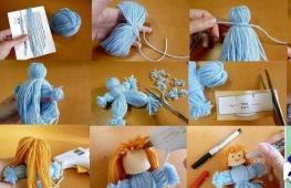
Greetings to all sewing lovers! Today I want to talk about a point that probably worries many beginning sewing masters. When sewing almost any product, one of the important operations is the processing of seams. In each case, it is performed differently, but most often using a special machine called an overlock. Not everyone has it, but they want the processing of all internal seams to be neat and beautiful. The lack of an overlocker is certainly an inconvenience, but not so tragic. Now I'll show you how to make an overlock stitch by hand. It will take more time than when working with an overlocker, but as a result you will get a very decent processing of all the wrong cuts.
In the comments, many readers write that the lack of a special device stops them from sewing any product. There was a time when I didn't have one either. I didn't even know what he looked like. I could only evaluate the result of his work on finished products.
I got my first overlock machine 24 years ago. It was called “Krosh” and looked like a toy mechanism. It rattled terribly and frightened me with the slightest malfunction. During the next repair, the master said that, in his opinion, this was not a sewing device at all, but a misunderstanding, and he successfully broke it (.
There was nothing left to do but buy a new overlocker. It turned out to be the Chinese version, which was much better than the previous one and served me for quite a long time. It was very heavy because it was completely made of iron. But at some point I wanted something even better, and I chose one of the company’s models Janome. So far I am quite happy with it and working on it brings me only pleasure.
Here is a short excursion into the history of my communication with overlockers. So at the beginning of my sewing experience, I was also forced to somehow adapt and look for ways to process fabrics without having special equipment. That's when I came up with this processing option, which is very similar to a real overlock stitch.
It should be noted that it is always easier to manually process dense and not very frayed fabrics than thin and loose ones. First of all, you need to cut off the seam allowance very evenly and carefully, and perhaps do it gradually so that it does not have time to fan itself.
For a sample, I took a thick strip of cloth and bright threads so that you could see it better.

I recorded the whole process in the photo and invite you to familiarize yourself with it. It will be more difficult to tell than to show, but I will still insert some comments.


In principle, you can finish processing the slices here, leaving them in this form. But if you want the seam to be as close in appearance as an overlock stitch, then you can perform several more simple operations. Namely, walk along the edge in a similar way.


Well, our overlock stitch, made by hand, is ready. It turned out quite well. I hope you liked it too. As you can see, there is nothing complicated, just a little effort and time.
I think that now you will not have good reasons to refuse the desire to sew yourself a new thing. In you will find some products that you may like and want to add to your wardrobe.
I would be grateful if you leave your comments and perhaps tell us about your experience.
Find out even more interesting things:

DIY head wreath made of decorative flowers
Hair jewelry is very popular now. They are worn by all female representatives, from young to old. Some of the original accessories are wreaths and headbands, ...

Such a rack, despite its apparent simplicity, is quite functional. It can not only be used to place books and various dust collectors, but also to zone space, for example, as a partition in a room. This is what various online furniture stores offer us.

In short, today we will build such a rack together with you. By the way, this is an ideal product for beginners: it is assembled on, (although it would be better on - they are not visible) there are elements of pipe systems, with all that, the product is quite large - this is not some kind of shelf for you!!!

Drawing with dimensions

The design is openwork without massive elements, but nevertheless quite rigid. I couldn’t find the original fittings (addition to the joker system), so I decided to use a pipe system to create such elements.
Rack detailing
Material consumption is slightly less than half of a standard 16 mm sheet 2750x1830 mm. 0.4 mm edges are consumed 16 meters. Let's add to this 3 meters of Joker pipe, 20 flanges with self-tapping screws and 20 confirmations with plugs.
I think that just in case, it is advisable to “grab” such a rack to the wall for greater stability.
This rack is sold in the store for 4,000 rubles. Naturally, I made it cheaper - for 3,500 rubles. If you are going to make it for yourself, you will spend about 2000 rubles, and you can make as many as two.
This is what I got using the Joker system with standard flanges. 
Silk yarn will come in handy in the wardrobe of a fashionista of any age and will make an excellent pair with both jeans and a classic skirt.
DIMENSIONS:
S (M) L (XL)
YOU WILL NEED:
100% silk yarn; 50 g/125 m) - 9 (10) 11 (12) skeins of white; knitting needles No. 3.5; circular knitting needles No. 3, 40 cm long; hook No. 2.5.
PRODUCT WIDTH BY CHEST:
84 (92) 100 (108) cm
LENGTH OF THE PRODUCT:
58 (60) 62 (64) cm
KNITTING DENSITY:
26 p. x 34 r. = 10 x 10 cm, knitted in stockinette stitch with knitting needles No. 3.5.
24 p. x 34 r. = 10 x 10 cm, knitted in an openwork pattern with knitting needles No. 3.5.
IMPORTANT!
The knitting density must be as specified! If the instructions indicate only one number, then it applies to all sizes!
ZIGZAG LACERY PATTERN
Knit according to the following pattern
Legend:
IMPORTANT!
If you can make only one yarn over at the edge of the part, but there are not enough loops to make a decrease to compensate for it, or, conversely, you can only make a decrease without a yarn over to compensate for it, knit on the outer loops with stockinette stitch.
The number of loops as a result of decreasing/adding loops in the pattern should not change, therefore, when performing decreases/increases, make sure that the number of yarn overs made is equal to the number of decreased loops.
COMPLETING OF THE WORK
BACK
On knitting needles No. 3.5, cast on 118 (120) 132 (144) sts, knit 4 r. with an elastic band (= alternately purl 2 and knit 2; 1st row - purl row) and continue working with stockinette stitch with a zigzag openwork pattern according to the pattern. Important: in the 1st row, decrease the stitches evenly so that there are 99 (109) 119 (129) sts on the needles.
When the length of the part is 6 cm, decrease on both sides: knit 1, knit 2 stitches together, knit until the last 3 stitches on the knitting needle, slip 1 stitch, knit the next loop and pull the removed loop through the knitted one, knit 1 . Repeat decreases every 12th row, complete 3 rows with decreases in total.
When the length of the back is approximately 18 (19) 20 (21) cm, add 1 stitch on both sides (= after/before the edge), in total, perform 3 rows with increases.
When the length of the back is 37 (38) 39 (40) cm, make a mark in the middle of the part and close it with
both sides at the beginning of each row for armholes 3, 2, 2, 1, 1, 1 (4, 3, 2, 1, 1, 1, 1) 4, 3, 3, 2, 1, 1, 1, 1 (5, 4, 3, 2, 2, 1, 1, 1) sts = 79 (83) 87 (91) sts left on needles.
When the height of the armhole from the mark is 19 (20) 21 (22) cm, close off the middle 37 (39) 41 (43) sts for the neckline and finish both sides separately. To round the neck, close from the inner edge at the beginning of each row, 3.2 stitches. At the same time, close from the outer edge
for the shoulder bevel at the beginning of each row, 5, 5, 6 (5, 6, 6) 6, 6, 6 (6, 6, 7) loops.
BEFORE
Knit like a back, but only with a deeper neckline: when the last 12 cm remains to be knitted to the end of the part (check along the back - to the last closed loops of the shoulder bevel), close the middle 15 (17) 19 (21) sts and finish both sides apart. To round the neck, close from the inner edge at the beginning of each row 4, 4, 3, 2, 1, 1, 1 p. Having knitted to the first closed loops of the shoulder bevel (check along the back), close the loops in the same way.
SLEEVES
On knitting needles No. 3.5, cast on 62 (66) 70 (74) sts and knit with an elastic band as described for the back. Continue working in stockinette stitch with a zigzag openwork pattern according to the pattern. Important: in the 1st row, decrease the stitches so that there are 60 (64) 68 (72) sts on the needles.
When the sleeve length is approximately 12 (10) 8 (6) cm, add 1 stitch on both sides (= after/before the hem) in every 10th row. Increase until there are 74 (80) 86 (92) sts on the needles.
When the length of the sleeve is approximately 32 (33) 34 (35) cm, begin to form the okat. To do this, close off 3.2 stitches on both sides at the beginning of each row, then decrease: in knits. row, knit 1 stitch, knit 2 stitches together, knit until the last 3 stitches on the knitting needle, slip 1 stitch, knit the next stitch and pull the slipped loop through the knitted one, knit 1 stitch. Repeat these decreases in every 2nd knit. row 4 times, then perform in each front row until 30 (32) 34 (36) stitches remain on the knitting needles (applies to all sizes). Then close on both sides at the beginning of each row 2, 3, 4 stitches and after that the remaining loops in one row.
ASSEMBLY
Sew the parts on the front side with mattress and knitted seams = mattress - longitudinal edges of the parts (= 1 r. x 1 r.), with a knitted seam - edges with closed loops. Sew shoulder, side and sleeve seams. Make sure that no folds form in the sleeve hem area.
NECK TRIM
On circular needles No. 3, cast on stitches from the front side along the edge of the neckline. Start from the right shoulder seam and pick up approximately 1 st from each closed loop along the edge of the back neckline. On the straight section of the left side of the front, cast on 1 p. from each row, skipping every 5th row, where one loop is closed, cast on 1 p. from each closed loop + 1 p. In other areas with closed Using loops, cast on 1 p. from each closed loop. On the other side of the front, cast on the loops in the same way (the total number of loops should be a multiple of 4). Knit in the round with an elastic band (= alternately knit 2 and purl 2), perform 4 rows in total. and close the loops.
CROCHETING
Using a size 2.5 crochet hook, tie all the edges on the elastic sections. To do this, knit 1 tbsp. non-cash between 2 persons. = 2 rub. down, perform 3 ch. and 1 connecting st. back between the same 2 persons, *1 connection. Art. between the next 2 purl, then between the next 2 knits. (= 2 r. down) = 1 connection. Art., 3 vp., 1 connection. st.*, repeat from * to * and close the row with the connection. column.

A zigzag attachment for a sewing machine is an ingenious device that simulates the execution of a zigzag stitch with a conventional straight-stitch machine like Podolsk, a stitch that was not initially revised by the design of the machine.
You should not buy such an attachment, since it will not be able to perform a high-quality zigzag stitch. But if you already have such a console, let's figure out how to use it.
Design and connection of the zigzag attachment

The structure of the zigzag attachment is quite complex, but its operation can be explained quite simply. To form a zigzag stitch, it is not the sewing needle that deviates to the side (right, left), but the fabric. Such an ingenious solution is provided by the complex operation of this mechanism, which makes no sense to describe.

The attachment is attached in the same way as other legs, by tightening the screw securing the foot leg.
On the other hand, the fork of the device is inserted behind the needle fastening screw.
The needle bar, moving up or down, lowers and raises the fork of the device accordingly. The fork imparts certain movements to the attachment, resulting in an offset stitch that looks like a zigzag stitch.

This is what is written in the instructions for the zigzag attachment.
The zigzag attachment for household straight-stitching machines is designed for making zigzag seams on cotton, linen and silk fabrics. Most often it is used when performing the following operations: sewing lace and ribbons, finishing the edge of the fabric without the seam going beyond the edge.

But the most important thing to pay attention to is written here.
The attachment is used with household sewing machines of classes 2M, 102 of the Podolsk Mechanical Plant, as well as with machines of some foreign companies with a distance between the axes of the needle bar and the rod of the presser foot equal to 14 mm.

This photo shows another “miracle attachment” that performs an overcast stitch. Naturally, this is more like a circus act and refers to funny inventions and devices, nothing more.

An overlock stitch cannot be replaced by any lockstitch sewing machine, much less various kinds of devices and devices. Including the so-called overlock sewing machine. But a high-quality imitation of an overlock stitch can be created using a special foot like this.
This foot can only be installed on a sewing machine that performs a zigzag stitch.
The zigzag attachment is installed only on an old-style lockstitch machine.
Special sewing feet and other devices greatly increase the capabilities of even the simplest sewing machine model.
This article contains reviews from a service technician about some modern and old models of sewing machines. In addition to household machines, there are also reviews about industrial models of sewing machines. There are several reviews about overlockers, carpet lockers and even furrier machines.
To work with genuine leather, you need special tools, devices for installing accessories, adhesives and other applied materials.
Each model of household sewing machine has its own set of feet. A detailed description of the use of feet for household sewing machines from Janome.
What is the difference between a round knife for cutting fabric and tailor's scissors? How to use OLFA circular knives, sharpen the blade, etc.