Design of the portal and vertical Z axis of a CNC engraving and milling machine. Four-axis machining on a machine with a rotary axis That’s all about the kit, now about the modifications
After considering the design options for the long axis - X - we can move on to considering the Y axis. The Y axis in the form of a portal is the most popular solution in the community of hobby machine tool builders, and for good reason. This is a simple and quite working, well-proven solution. However, it also has pitfalls and points that need to be understood before design. Stability and correct balance are extremely important for the portal - this will reduce wear on the guides and gears, reduce the deflection of the beam under load, and reduce the likelihood of wedging during movement. To determine the correct layout, let's look at the forces applied to the portal during operation of the machine.

Take a good look at the diagram. The following dimensions are marked on it:
- D1 - distance from the cutting area to the center of the distance between the portal beam guides
- D2 - distance between the X-axis drive screw to the bottom guide beam
- D3 - distance between Y-axis guides
- D4 - distance between X-axis linear bearings
Now let's look at the actual efforts. In the picture, the portal moves from left to right due to the rotation of the X-axis drive screw (located at the bottom), which drives the nut fixed on the bottom of the portal. The spindle is lowered and mills the workpiece, and a counterforce appears directed towards the movement of the portal. This force depends on the portal acceleration, feed rate, spindle rotation and kickback force from the cutter. The latter depends on the cutter itself (type, sharpness, presence of lubrication, etc.), rotation speed, material and other factors. A lot of literature on the selection of cutting modes is devoted to determining the magnitude of kickback from a cutter; at present, it is enough for us to know that when the portal moves, a complex counterforce F arises. The force F applied to the fixed spindle is applied along the structural elements to the portal beam in the form of a moment A = D1 * F. This moment can be decomposed into a pair of equal in magnitude, but oppositely directed forces A and B, applied to guides #1 and #2 of the portal beam. Modulo Force A = Force B = Moment A / D3. As can be seen from here, the forces acting on the guide beams decrease if D3, the distance between them, increases. Reducing the forces reduces wear on the guides and torsional deformation of the beam. Also, with a decrease in force A, the moment B applied to the sidewalls of the portal also decreases: Moment B = D2 * Force A. Due to the large moment B, the sidewalls, being unable to bend strictly in the plane, will begin to curl and bend. Moment B must also be reduced because it is necessary to strive to ensure that the load is always distributed evenly across all linear bearings - this will reduce elastic deformations and vibrations of the machine, and, therefore, increase accuracy.
Moment B, as already mentioned, can be reduced in several ways -
- reduce force A.
- reduce leverage D3
The goal is to make the forces D and C as equal as possible. These forces consist of a pair of forces of moment B and the weight of the portal. For proper weight distribution, it is necessary to calculate the center of mass of the portal and place it exactly between the linear bearings. This explains the common zigzag design of the sidewalls of the portal - this is done in order to move the guides back and bring the heavy spindle closer to the X-axis bearings.
In summary, when designing the Y axis, consider the following principles:
- Try to minimize the distance from the X-axis drive screw/rails to the Y-axis guides - i.e. minimize D2.
- If possible, reduce the spindle overhang relative to the beam, minimize the distance D1 from the cutting area to the guides. The optimal Z stroke is usually considered to be 80-150 mm.
- Reduce the height of the entire portal if possible - a high portal is prone to resonance.
- Calculate in advance the center of mass of the entire gantry, including the spindle, and design the gantry struts so that the center of mass is located exactly between the X-axis guide carriages and as close as possible to the X-axis lead screw.
- Space the portal guide beams farther away - maximize D3 to reduce the moment applied to the beam.
Z AXIS DESIGN
The next step is to select the structure of the most important part of the machine - the Z axis. Below are 2 design examples.

As already mentioned, when building a CNC machine, it is necessary to take into account the forces generated during operation. And the first step on this path is a clear understanding of the nature, magnitude and direction of these forces. Consider the diagram below:
Forces acting on the Z axis

The following dimensions are marked on the diagram:
- D1 = distance between Y axis guides
- D2 = distance along the guides between Z-axis linear bearings
- D3 = length of the movable platform (base plate) on which the spindle itself is mounted
- D4 = width of the entire structure
- D5 = distance between Z axis guides
- D6 = base plate thickness
- D7 = vertical distance from the point of application of cutting forces to the middle between the carriages along the Z axis
Let's look at the front view and note that the entire structure moves to the right along the Y-axis guides. The base plate is extended as far down as possible, the cutter is recessed into the material and during milling a counterforce F arises, directed, naturally, opposite to the direction of movement. The magnitude of this force depends on the spindle speed, the number of cuts of the cutter, feed speed, material, sharpness of the cutter, etc. (we remind you that some preliminary calculations of what materials will be milled, and therefore an assessment of the cutting forces, must be made before the beginning of machine design). How does this force affect the Z axis? When applied at a distance from the place where the base plate is fixed, this force creates a torque A = D7 * F. The moment applied to the base plate is transmitted through the Z-axis linear bearings in the form of pairs of transverse forces to the guides. The force converted from the moment is inversely proportional to the distance between the points of application - therefore, to reduce the forces bending the guides, it is necessary to increase the distances D5 and D2.
Distance D2 is also involved in the case of milling along the X axis - in this case a similar picture arises, only the resulting moment is applied on a noticeably larger lever. This moment tries to rotate the spindle and the base plate, and the resulting forces are perpendicular to the plane of the plate. In this case, the moment is equal to the cutting force F, multiplied by the distance from the cutting point to the first carriage - i.e. the larger D2, the smaller the moment (with a constant length of the Z axis).
Hence the rule follows: all other things being equal, you should definitely try to space the Z-axis carriages further away from each other, especially vertically - this will significantly increase rigidity. Make it a rule to never make the distance D2 less than 1/2 the length of the base plate. Also make sure that the thickness of the D6 platform is sufficient to provide the desired rigidity - this requires calculating the maximum operating forces on the cutter and simulating the deflection of the insert in CAD.
Total, adhere to the following rules when designing the Z axis of a gantry machine:
- maximize D1 - this will reduce the moment (and therefore the force) acting on the gantry struts
- maximize D2 - this will reduce the moment acting on the portal beam and the Z axis
- minimize D3 (within a given Z stroke) - this will reduce the moment acting on the beam and the portal posts.
- maximize D4 (the distance between the Y-axis carriages) - this will reduce the moment acting on the portal beam.
Part two:
Part three:
Part four:
Part five:
Part six: machine electronics
Well, a separate plus is linear bearings immediately in the housing, since they are easier to install on homemade structures. Simple LM08UU are cheaper, but you need to make a holder for them (can be printed on a printer) - this is a separate conversation. 
So, a few words about the set of components for the new Y-axis itself, then about the modification. Received the parcel 3 weeks after ordering, in a postal bag and a narrow cardboard box for strength. This is a plus, the cylindrical shafts just fall out of the package, for some reason the sellers on Ali don’t think about this. But in vain. 
Each item in the set is packaged separately in a bag. There are traces of oil in the bearings 
To estimate the scale, I attached a ruler to the guides and screw. Ruler 30 cm, iron 40 cm 
The ends of the screw and shafts are without burrs. It feels like the shafts are cut into standard sizes using a large whip, as you can see a little bit of soot on the end. But processed after cutting. In principle, I can carry out the same operation myself, so I try to take as long sections as possible. 
The ends are chamfered. If you cut it yourself (and I cut it a little to size), then the chamfer can be removed on a sharpener/by hand. It is mainly decorative so that there are no burrs and when installing bearings it does not touch the balls. 
I didn’t catch microns, the shaft diameter is quite 8 mm. There are no questions about the manufacturing accuracy of cylindrical shafts, the main thing is that they are not bent upon delivery. I have more complaints about the bearings. I bought several lots of cheap LM08UU from Ali, and some are tight, and some are slightly loose. This is noticeably noticeable on bearings, especially if installed on the same shaft. 
SK8 calipers are a convenient thing. They are installed directly on the profile (any), and the shaft is clamped. If desired, it can be used in amateur designs, for clamping anything with a diameter of 8 mm (for example, a center for a machine). 
Overall and installation dimensions are not a problem to find, they are standard. If necessary, write in a personal message or look in the first two topics, there were drawings there. 
Initially, when trying on the design and before ordering, I used 3D printed supports. I have now removed it because it is no longer needed. With metal ones it turns out much better e stche design 
KP08 bearing supports for fixing the lead screw. There are two 1.5 hex screws for the clamp.
These supports are very convenient to use in amateur designs: they are used in 3D printers for the Z axis, and you can also make homemade belt drives by clamping an 8mm shaft section in this bearing and installing a gear on the shaft. Please note: this CNC2417 replica uses KFL08 flange bearings to install the T8 screw on the plate on the X axis. 
And last but not least, the SC08UU housing linear bearing. It costs a little more (twice) than the simple LM08UU, but it has an M4 thread for installing mounting screws. It is also very convenient to use in amateur designs due to the ease of installation. There is a version SC08LUU, extended, which I use in the Z-axis slider. 
That's all about the kit, now about the modifications.
I started the assembly with the X and Y axes, and the carriages, respectively.
First, we assemble the Y axis: engine, caliper, screw with nut and coupling.
We install the engine on the holder. It's simple: four M3 screws. The length is short, mainly depends on the plate used (thickness) and washers. 
Motor with plate before installation on the profile. 
Next, install KP08 opposite, keeping the distance from the center of the engine axis and from the center of the caliper axis the same 

Next, we install the SK8 shaft supports, four of them, a pair per shaft. When installing shafts, do not forget about bearings. 
Next, we assemble the plate with the X motor, as well as the plate with the KFL08 caliper 
The plates are made symmetrical, and you can assemble the propeller on both sides on the KFL08, having previously installed the engine on (M3 Brass Spacer - convenient to take in sets). 
Initially there was a 3D printed KFL08, but while I was assembling and testing I managed to order and receive a normal one))) 
We further assemble the X axis. Install the plates on the frame 
Install the second plate.
The plates provide additional rigidity to the structure and at the same time serve as a holder for the X axis. For reinforcement, 3 8 mm cylindrical shafts were used. 
Next, we install shafts (three pieces) plus SC08UU bearings (three pairs, respectively) into the holes of the plates. 

Closer photo. 10 mm of cylindrical shaft on each side is clamped into the SHF08 caliper. And it is advisable to leave about 20 mm of the lead screw for installing the handle (manual movement of the carriage). 
We install the plate-carriage X on the bearings. Don't forget about the nut. I used a 3D printed nut holder. Buying a holder is quite problematic. The options to buy are either a flat plastic nut (POM) with holes for fastening (options and). I saw them on sale, but they cost a lot of money. So for now the printed holder... 

We check the free movement of the carriage from the beginning to the end of the axis, tighten the screws. 
The Z-axis slider is already attached to the plate. You can make them from a section of 2080 profile and SK8 calipers, you can make them yourself, you can
With numerical control, enhancing the production features of the working tool. It allows you to process non-standard workpieces, producing products of complex shapes. The equipment makes it possible to carry out full-fledged 3D and 4D processing on CNC machines. Most often, the unit is used to work with wood, but it can also process other materials.
Peculiarities
Rotary axes are not typical for every machine. The main task of this element is to ensure rotation of the workpiece around its axis. It is used to process workpieces based on:
- tree;
- aluminum, non-ferrous and copper alloys;
- plastic.
The engine is responsible for the operation of the axis. It may be part of the original machine design, or installed separately. When installed separately, the element acts as a fourth axis.
Four-axis processing, unlike three-axis processing, has a number of advantages. The three-axis method makes it possible to perform 3D processing on one side of the workpiece, since the other will be attached to the table. To process the second side, you have to perform additional steps to reinstall the product. The rotary axis solved this problem. With its help, the workpiece can be processed from all sides without additional actions.
Thanks to this feature, it is possible to obtain products with a complex design:
- furniture components;
- jewelry;
- decorative wooden patterns.
Machines with a rotary axis are widely used in decorative applications. Correct setup of the device will allow for offline processing. The blanks will be similar to handmade products.
Design
There are various options for machines with a rotary axis. The highest quality are . Performance on conventional devices is lower.
On high-performance units, a belt drive is installed. Some models are equipped with a fifth axle. The dimensions of the desktop may vary, but the width and length should not be less than one meter. Homemade devices are characterized by installation of a lathe chuck or faceplate on the rotary axis. Three-jaw lathe chucks are common on factory machines.
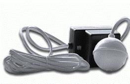
The most popular type of motor is a two-phase four-wire motor.
Dimensions and cost of equipment depend on the specific model. Large-sized options are used in industrial environments. More compact models can be used for household tasks and small businesses. But not everyone can afford even the cheapest options. Therefore, many people make a CNC machine on their own.

Do-it-yourself machine with a rotary axis
Inexperienced users are not recommended to make a machine with a rotary axis from metal. Initially, you should try to make a unit from plywood. At the first stage, a drawing and a control milling program are drawn up. This step can be completed using the Rhinoceros service. The thickness of the plywood must be at least 15 millimeters. It must be fixed on the table, after which the CNC machine will make the necessary blanks.
The second stage consists of assembling the resulting parts. After this, you need to purchase a water pump bearing. This item is sold in auto parts stores. Before installing the bearing, the parts must be coated with paint and varnish. The bearing can be strengthened with bolts. To operate the device, you will need a group of components, including:
- machine table;
- Belting;
- stepper motor.
Additional parts are made on a lathe. After the assembly of the unit is completed, you will need to separately purchase a driver responsible for controlling the stepper motor. The new driver must be installed in the machine control unit.
Before a self-made CNC rotary axis is launched, you need to make sure that the components are well secured.
Usage
There are two ways to work with a rotary axis:
- index;
- continuous.
The first method involves step-by-step processing, starting with free movements and ending with stationary conditions. The transition from one processing to another is accompanied by a stop and fixation. For the second method, no additional steps are required. Correct processing depends on the availability of the program and a suitable model of the working tool.
For complete processing, the machine must be equipped with a four-axis control system. To compensate for the weight of the spindle, the Z axis is equipped with a gas spring.