How to make a faucet by hand drawings. Do-it-yourself crane - how to make it from scrap materials
Materials for the crane were mainly found in scrap metal. We only had to buy bearings, a winch, and order parts for the turning mechanism from a turner.
And I also had to pay a welder, since I myself cannot do welding work, due to some vision problems.
In general, this crane cost 5,000 rubles, which cannot be compared with the amount of work that I managed to complete with its help, because the “cheapest” helper in our region costs 800 rubles per day.
I’ll immediately make a reservation that during operation, my faucet revealed some shortcomings, which I will point out and advise on how to correct them. So your faucet will be a little different from mine.
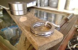
Let's start with the rotating mechanism

It consists of six parts that need to be ordered by a turner, and two bearings.

As you can see, there are no dimensions in the drawing. The fact is that you don’t have to follow the exact size, like mine. After all, we make the faucet from available material, and I cannot know what size channel or I-beam, or what kind of pipe you will have at hand.
A little more or a little less doesn’t matter in my design. And you will understand this from further instructions. And having generally estimated what materials and parts you have, determine what dimensions to take for the manufacture of the rotating mechanism.
The mechanism has two bearings. At the top, between the housing and the base, there is a support bearing. Below, again between the housing and the base, there is a simple radial bearing.


Or rather, the housing should be mounted on the bearing, and the base should fit into it. Thus, both of these parts are connected. For more reliable fixation of the radial bearing, a nut is screwed onto the housing from below. The thickness of the threaded and retaining parts of the nut is at your discretion, but not less than 3 mm.
Then this unit is attached to the platform with a bolt (I have an M 26), which attracts the base to the platform. Thus, it turns out that the platform and base are a stationary part of the mechanism, and the body with the nut is rotating.
Now a little about what practice has shown. Towards the end of the season, the radial bearing weakened a little, and a barely noticeable play formed in the turning mechanism.
But with a boom length of 5 meters, this play became noticeably noticeable, so I recommend installing a hub bearing, 36 mm wide, instead of a radial bearing.


Here in Kazan, support and wheel bearings can be bought for 500 rubles both. And to tighten the bolt securing the base to the platform, you will need a spanner with an extension, and definitely two washers - a flat one and a lock washer.
Our next node will be the rack.


To make it you will need a piece of pipe (I have d140) and four pieces of channel. You need to estimate the height of the stand so that when finished it will be just right for you. Even two centimeters lower. Then it will be convenient to turn the winch when operating the crane.
Since God is unlikely to send you a piece of pipe with an evenly cut end, you will have to cut one end yourself. To do this, we take a car clamp, or make a clamp from a strip of tin, and tighten it on the pipe.
When tightened, the clamp will try to position itself on the pipe as evenly as possible, and if you help it a little (by eye), you will get a fairly even line around the circumference of the pipe, which you just have to draw, then remove the clamp, and cut the pipe along this line using a grinder .
Then, the rotating mechanism platform is welded to this flat end of the pipe. Now it’s clear why I didn’t give the dimensions in the drawing? You still have to order the rotating mechanism. And you can find a tuba. This means the diameter of the platform can be ordered according to the diameter of the pipe.
Now the legs. They need to be welded so that the stand does not collapse. How to do it? Firstly, they need to be cut to the same length.
Then hang the pipe with the welded platform, passing the rope through the hole in the center of the platform, and place your legs diagonally towards the pipe, so that in the end, the pipe remains hanging evenly, and your legs rest against it on all four sides.
As soon as the balance is found, you need to draw by eye the corners of the channels that abut the pipe, and trim them with a grinder as shown in the photo.
After trimming the corners, lean your legs against the pipe again, catch your balance, check with a rack and tape so that they form an even cross, and secure them with welding. After tacking, check the cross again, and you can weld.
All that remains is to make the support cross itself. It can be made from any rigid profile. At first there was an idea to put it on wheels made of bearings, but time was running out, and it didn’t come to the wheels, but actually it would have been nice. The unit turned out to be quite heavy, and it was difficult to move it.


The length of the arms of the cross is 1.7 meters, although as operation has shown, this cross does not play a particularly large role in the stability of the crane. The main stability is provided by balance, which we will talk about later.
The cross is not welded to the legs, but is attached with M 10 bolts and nuts. This was done for ease of possible transportation. The legs were reinforced in anticipation of installing wheels, but they never got around to it, although the idea of installing them is still there.
The stand with the rotating mechanism is ready, now let's move on to the crane platform, on which the counterweight, winches, and boom will be installed. I found a one and a half meter I-beam, 180 mm wide, for the platform. But I think you can use a channel and even a 150 x 200 beam under it.

At first I even wanted to use timber, but since I found an I-beam, I chose it. The platform is attached to the rotary mechanism body with four bolts and M 10 nuts.


If you use timber instead of an I-beam, then you will need to make additional platforms for it, above and below. You can “encircle” it with two pieces of channel and tighten everything with bolts.
But we’ll wait with the bolts for now, since the place where the platform is attached to the rotating mechanism will need to be selected based on balance. That is, the crane boom must be balanced by a block for counterweights and a winch. That is, the crane must stand confidently on the stand and not fall over.
Next will be the counterweight block.


I have it made from pieces of the same channel as the platform, but it can be made from anything, and in any way. The main thing is to have a container in which you can install loads, so that if necessary, you can increase the counterweight.
Now about the winch. My winch is installed with a capacity of 500 kg, with a brake. And once again, as practice has shown, such power was not enough to lift a load of about 100 kg.
That is, you can lift it, but you have to lean so hard on the handle that when lifting to a height of more than 5 meters, you get tired very quickly. For such a crane you need a winch of 1 - 1.5 tons.
There was also supposed to be a second winch for lifting the boom, but at that time, having visited a bunch of shops and markets, I could find only one winch with a brake, which you see in the photo. Therefore, instead of a second winch, a temporary tension cable was made, the length of which is still changed using clamps.


Unfortunately, there is nothing more permanent than a temporary structure. I still recommend that you install a winch instead, preferably a worm one. Its speed is low, and the brake, whether up or down, is dead. That's what an arrow needs.
All that remains is to make an arrow, which is what we will do. The boom consists of a mount with a shaft, a beam 150 x 50, and a tip with a pulley.


First, the mounting body. It is better to make it from a piece of channel wood.


Any round timber with a diameter of 20 to 30 mm will do for the shaft. For example, I cut off a piece of the rotor shaft of some old engine. Then we bend it in a vice, put two brackets around this shaft and fasten it to the channel, into which the beam will then be inserted.


We buy two simple bearings, so that they fit tightly onto the shaft, and cut out a seat in the mounting body.


Of course, you can dream up how to secure the bearings in the housing. Besides mine, there are probably a dozen more ways. And I found an ebonite plate, 10 mm thick, from which I made these fasteners.


The boom itself is a beam 150 x 50, 5 meters long. It is inserted into a channel 80 mm wide and 2.5 meters long. True, I had to trim it a little so that it would go inside the channel. I have a channel installed, 3.5 meters long, but this is only because at that time there was no good timber at hand with small knots. I simply played it safe, which, unfortunately, increased the weight of the arrow.
The timber is secured to the channel with ties made from a metal strip 3 mm thick.

At the end of the boom, you need to attach a pulley for the cable. Mine is made from a wheel from a trolley bag. For skilled hands, I think there are plenty of options for attaching the pulley. At first it was fastened between two pieces of plywood, but then I made a fastening from a channel.


Now you can assemble the arrow, if not for one “but”. During operation, the brackets with which the shaft is attached to the channel turned out to be rather weak. So I made them stronger.


And one more addition. My reinforcing part is secured with four bolts. You need to add two more on top to make the unit more rigid. Although mine works fine with four bolts. Otherwise I would have added it a long time ago.
Now you can assemble the entire crane platform, that is, install a winch on it, a block for counterweights under the winch, and at the other end - a boom lifting body with a boom. If there is, then a second winch, if not, then a guy rope, like I have.
All this is assembled in a lying position, and upon completion it is raised vertically, onto some kind of support. For example, I stacked several pallets on top of each other and placed the assembled platform on them so that the counterweight hung freely downwards.
Then we attach the rotating mechanism to the stand. The most important thing remains - install the platform on the stand so that the boom and counterweight balance each other.
Unfortunately, I don’t have any photographs of the structure that I built for this, well, I’ll try to explain it this way.
This design is a tripod with a block at the top. The height of the tripod is approximately three meters. It is made from 100 x 50 timber. As you probably already guessed, the assembled crane platform needs to be suspended and raised so that a stand can be placed under it.
The platform will be raised using its own winch. To do this, we pass the winch cable through the block and hook it to the boom lifting body, which is located at the opposite end of the platform.
Now, if you operate the winch upward, the entire platform will rise. But during the rise, the arrow, raised up, begins to collapse, so you need to either call a couple of assistants who will fix the arrow in a vertical position, or make another tripod (as I did) with a block 6 meters high, and tie rope to the end of the arrow, let it through the block, and pull it up as the platform rises.
Having suspended the platform in this way and placed a stand under it, you can lower and raise the platform and move the stand to find a position in which the counterweight will balance the boom.
In this position, drill 4 through holes and bolt the platform to the rack. OK it's all over Now. The tap is ready. You can start testing.
Well, a couple of examples of operation:


General view of my faucet:

If the article does not answer your question, ask it in the comments. I will try to answer as quickly as possible.
I wish you success in your work, as well as the opportunity to lift and move everything you need and where you need it.
Users of the portal share their experience in building homemade lifts from simple to complex structures.
When building a house from aerated concrete, timber, brick, etc. There is often a need to lift a load. For example, you need to “throw” blocks or wooden beams onto the second floor, lift bags of cement, or pour an armored belt. Doing this manually, even with the help of assistants, is not so easy - health is more expensive. Hiring a truck crane or manipulator for a small amount of work is expensive. The solution is to use a mini-crane, which, to reduce the cost of construction, is made by hand.
- How to make a lift for laying aerated concrete.
- What parts and tools are needed to build a mini crane.
- How to reduce the costs of building a universal lift.
Lift for laying aerated concrete blocks
Abroad, during the construction of private houses, cranes and various lifts are often used. This way construction goes faster, which means the “box” is cheaper, because It is more profitable to use small-scale mechanization tools than to hire laborers. Our developer relies on himself and often builds a house “with one helmet.” Therefore, the urgent question is how not to physically overstrain yourself when laying a wall from aerated concrete blocks weighing 35-40 kg.
An interesting option is the unusual homemade “assistant” of the FORUMHOUSE user with the nickname Krestik. First, let's show what he took as a basis.

German mini crane with retractable central post
A special feature of the lift is the original folding “arm-boom”, with the help of which the crane, moving on wheels, can reach two opposite walls.

I am building a house myself and, in order to be able to lay aerated concrete blocks, I built a lift according to the above model. The crane was made completely collapsible, except for the base. I didn’t measure the maximum load on the hook, but it easily lifts me (weighing 95 kg).

Technical characteristics of the lift:
- width – 2200 mm;
- height – 4200 mm;
- boom radius – 4200 mm;
- load capacity of electric hoist – up to 800 kg;
- total weight of the crane with ballast is approximately 650 kg;
- lift weight without ballast – about 300 kg;
- The maximum lifting height of the masonry block is 3500 mm.

The working height of lifting blocks is adjustable in two ranges. The first is 1750 mm. The second is 3.5 m, for which the structure is raised, sliding upward along the supporting “legs” using a hydraulic jack lined with spacers made of GB blocks.

To make the lift, the user needed:
- swivel wheels;
- profile pipes for the mast, “legs” and boom with a section of 12x12 cm, 12x6 cm, wall 6 mm;
- pipe-jibs – 63x3 mm;
- powerful gate hinges;
- The boom rotating mechanism is made of ST45 steel and “205” bearings.

During operation, the design was modified. For example, the user laid the cable for the winch in a corrugated pipe and extended the cable for the control panel.

The design has a number of shortcomings that I would like to correct. For example, I’m thinking about making wireless control, replacing the gate hinges with bearings. Increase the number of “joints” in the boom at the same reach. Instead of a temporary counterweight - bags of sand concrete, pour concrete ballast.

Important nuance: in order for the lift to move around the construction site or, for example, over the concrete slab of the second floor, it is necessary to keep the workplace clean, because GB fragments and debris interfere with the relocation of the tap.

The design of the unusual lift attracted the interest of portal users.
Konstantin Y. Member of FORUMHOUSE
With such a lift, I think, as they do in Germany, you need to make masonry from blocks larger than standard ones. The length and height are 2-3 times greater than a regular GB. The crane has enough lifting capacity, and the laying speed will increase significantly.
According to Krestik, he heard that someone on the portal had already tried to order blocks of 1x0.4x0.6 m format from a gas silicate manufacturer. But it turned out that this was not profitable for the plant, because it is necessary to reconfigure the line for the production of GB, but for the sake of a small volume (for an ordinary private house) they will not do this.

Vegaroma FORUMHOUSE Member
I'm wondering: is the work on site easier when using a crane? What work can be done with it and what cannot?
There is no need to install scaffolding when laying GB walls. The lift can be assembled and disassembled. I poured the concrete lintels over the windows the old fashioned way, from buckets, because... The volume is small, and it’s easier to do it with one assistant.
Grand total: The mini-crane turned out to be successful, and with some modifications to its design, the lift can be put into small-scale production.

Mini crane made from scrap metal
Another version of a lifting mechanism made of metal “lying underfoot” was made by a portal participant with the nickname Petr_1.

According to Peter_1, the reason for the construction of the crane is that the house is getting higher and higher, and the blocks and concrete are getting heavier. Therefore, after revising the “unnecessary things”, the user manufactured a completely dismountable crane with a lifting capacity of 200 kg.
I think my crane can lift more, but I didn’t overload it. The crane can be disassembled into parts weighing 30-60 kg and can be easily transported in a car trailer. I carry an arrow on the trunk. Statically tested a structure weighing 400 kg. I usually lift up to 150 kg. This is quite enough for my construction needs.

At one time, the crane, with a boom reach of 5 m, lifts 10 blocks weighing 15 kg each, or four 15-liter buckets of solution.
The design of the crane is a hodgepodge of what was at hand. Let's list the main details:
- swivel unit - truck hub;

Hubs from cars, trucks, and farm equipment are often used to make the swivel assembly in homemade cranes. The main thing is to calculate the loads acting on it and the fasteners.
- the boom is made of a pipe with a diameter of 75 mm;

- outriggers and base - a rectangular pipe with a section of 8x5 and 8.5x5.5 cm;

- the base of the tower is the “200th” channel;

- worm gearboxes for boom and cargo winches.

- three-phase electric motor with reverse, power 0.9 kW, converted to power from a 220 V network;

The crane turned out to be mobile, and by lowering the boom, it can be moved from place to place, rolling on wheels along compacted soil. Level adjustment is carried out using screw supports.

Metal, gearboxes and rollers were purchased at a recycled metal shop. Only the cable and bearings are new.

The weight of the crane without counterweight is about 250 kg. The cost of the structure, taking into account the purchase of consumables - cutting discs for angle grinders, electrodes for a welding inverter and paint, is 4 thousand rubles.

Crane, + time for turning, + selection of components and fitting of components, I completed it in 3 working days. In the future, after finishing the work, I will completely disassemble it.

Inexpensive mini lift
Practice shows that when building a private house, a real crane is not always needed. Often, a developer can get by with “little expense” and make a small lift based on an electrically driven hoist.

Gexx FORUMHOUSE Member
My design is simpler than the authors above, but it suits me quite well. I bought a hoist with a load capacity of 300 kg without a block and 600 kg with a block. Tests have shown that the device can lift a load weighing 250-270 kg, then the engine protection is triggered. During the construction season, I used it to lift about 40 pallets with building blocks, a 6-meter beam for the mauerlat, rafters, mortar for masonry and concrete for the reinforced belt.

The lift, again to save money, is made from used pipes, angles and channels.

All rust was cleaned off with a grinder, and the pipes were sprayed and then painted with paint with a rust reducer.

In order to be able to assemble the lift on the ceiling of the second floor, all components (where welding is not needed) are made collapsible - with bolted connections.

A hoist is installed on the stand using clamps.

In case of rain, a plastic bottle with the bottom cut off is placed on the control panel.

The telpher covers a canopy made of used roofing iron.

When lifting a pallet, two boards are placed under it, and the pallet is lowered onto them.

The entire structure is fixed to the floor with clamps.

Drawing with dimensions of the lift.

As a result, the user has a universal, self-manufacturing and budget “helper” that greatly simplifies the work of building a house.

These are topics that describe in detail how to make a lift for aerated concrete, and provide dozens of options for mini-cranes, from simple to the most complex designs.
A crane is an indispensable thing during construction or repair, especially if you have to work with heavy building materials and the number of assistants is limited. It can serve as an indispensable device when lifting property and furniture to the upper floors of the house and will save you from dragging when moving. The construction of lifts can be done with your own hands from various available materials.
Crane for building a house and lifting beams and logs
Before starting construction of the lift, it is necessary to sketch out drawings to calculate the amount of materials. A crane for DIY construction should be easy to move and disassemble for transportation. It should not only perform the functions of a lift, but also be as much as possible:
- light;
- durable;
- sustainable;
- collapsible.
To make it lighter, the crane frame is welded from a pipe. It can move on three or four wheels at the discretion of the designer. There must be a place for a counterweight on the back so that the crane does not lose balance and fall when lifting a load.
After making the platform on wheels, a beam is installed diagonally to the ground level and a stand under it in the form of a support welded from pipes. If desired, the height of the boom can be made retractable and with the ability to raise or lower it for ease of operation.
At the bottom of the boom, a winch (manual or electric) is installed on the body so that the cable can be easily removed from the upper roller of the boom and it serves to pull heavy logs and timber to the crane for easy lifting.

A hook is installed at the end of the cable. Additionally, a special device is made for gripping logs and beams in the form of the letter "P". A rod is installed at the top in the center of this device to engage it with a hook. A clamp in the form of a screw is made on the side in the center, which will hold the building material.
When lifting a log or beam to the desired height, the crane on wheels easily rolls to the desired side, and the material is lowered into place for further installation and fastening. The lift structure must be on a flat, hard surface for easy movement.
Such lifting mechanisms help to carry out work efficiently and quickly with minimal physical exertion, which can be done by children.

Horizontal boom lift
A crane with a horizontal boom is manufactured as follows. A frame is welded from a pipe or angle crosswise on wheels, on which in the rear part it is necessary to make a place for a counterweight to avoid the loss of balance of the crane during operation and its fall. Wheels are installed on it for easier movement. The larger the frame area, the more stable the crane.
Stops are installed on its edges near the wheels to prevent movement during operation.
After manufacturing the frame, a mast is installed vertically in its center, on which the boom is fixed. The fastening must be strong, it must rotate around its axis.
An additional stop with a handle is attached horizontally from the vertical mast to rotate it. A place for attaching a manual or electric winch is installed on it. Another mast is additionally mounted vertically to the stop, which is attached from above to the boom to provide greater stability and strengthen its fixation.
At the top, a boom is attached to both masts, equipped at both ends with rollers for the cable, so that the central vertical support rests on the center of the boom, and the second, additional one, exactly in the center between the first mast and the rear edge of the boom.
A winch is placed on a horizontal support fixed to the second vertical mast.

Its cable first passes through the roller on the back side of the boom, then through the front roller with a hook at the end. The entire crane structure is assembled with utmost strength and can be disassembled for ease of transportation. A gripper is installed that lifts the blocks.

Design made from improvised materials for work in the garage
Such a homemade lift is especially needed for those who repair cars, forlifting or installing heavy machine components and assemblies.

The crane is assembled from a frame, which is welded from a pipe, an iron profile, and angles. It is easier to install them crosswise, since this arrangement provides greater stability of the crane. Wheels are attached to the edges for easy movement around the garage.
Many people are interested in how to make a crane structure with their own hands. Such a device can help in building a house, utility rooms needed on the farm, a granary and a feed warehouse.
Drafting
To build a house you need a crane. Let's look at how to independently make a miniature crane design for lifting construction loads to a height. It is necessary to manufacture a mobile dismountable device.

First, a design for the manufacture of the apparatus is drawn up and calculated:
- The main part of the structure is the supporting frame. It is installed on wheels or permanently.
- The rotation unit of the unit is fixed to the running frame.
- The boom can be rotated thanks to the creation of electric or manual control.
- The unit can be disassembled into parts for ease of transportation.
- The crane will be stable thanks to the creation of a block of counterweights and steel cable stays.
- The load will be lifted using a block and a winch.
- You need to assemble a crane with your own hands.
Blueprints
To make a crane, first of all, draw up a project diagram and drawings of the main components. Consider the manufacture of a manually operated crane structure. It would be possible to make a device powered by electricity, making it possible to move a load using a device on a long cable, as happens in factory designs. But then the complexity of manufacturing units increases, this will entail an increase in the cost of the finished product and an increase in the time for its creation. Therefore, we will focus on making a manual model.

Welding
All connections of components and parts are made by welding. For this you need a welding machine. You can rent it while working on the crane or buy it at a specialized salon.
Assembly of the structure
Prepare:
- rope;
- washers;
- corners and channels;
- pipe;
- grinder;
- welding machine.

The frame should be made of steel angle 63x63x5 mm. A 5 m long boom is made from a pipe having a diameter of 55 mm. To strengthen the unit, use corners measuring 30x30x3 mm.
The lifting capacity of such a homemade crane will be about 150 kg. If it is necessary to lift panels with a larger mass, then it is necessary to increase the multiplicity of pulleys, which are a device for lifting loads. The chain hoist is made from blocks, connected to each other with a cable. This cable should wrap the blocks in a circle. The pulley allows you to lift the panels using less force than the weight of the load.
The pulley system is 3-4 times stronger. In this case, friction losses are taken into account, which amount to 10%. The greater the gain in strength, the shorter the distance the tool can move the panels.
You can prepare and make all the details in 7-10 days.
Another 2 days are needed to assemble the mechanism. The lifting scheme is made in the form of a 2-fold pulley. The boom rotation unit is a 6-fold chain hoist. The turntable is made by attaching 2 washers. The axle replaces the 30mm bolt.

To reduce the size of the counterweights, the support legs are made 2 m long. With a turning radius of the washer of 200 mm and a distance of 2 m to the counterweight of 100 kg, a load of 1 ton will be applied to the bolt. This is taken into account when calculating the design of the tool. Perform stability calculations.
The structure is taken as a single system on one support. It is the smallest distance from the axis of rotation. The system is affected by: the weight of the load, the counterweight and the crane. The lifting drum is made from a pipe with a cross-section of 100 mm. It should not be installed close to blocks. It is fixed closer to the washers.
Blocks are made of 3 washers. They must be wrapped around the cord, the diameter of the blocks must be large so that the ropes do not fly out of the washers. The blocks are fixed without bearings.
You need a flexible cable with a cross section of 5 mm. Its working load is 150 kg, and its breaking load is 850 kg. The pulley operates on the principle of a lever. For a chain hoist, the main indicator is its multiplicity (the ratio of all cable branches to those extending from the drum).
If the cord has 6 parts, then the pulling force on the drum will be 6 times less than the weight of the load. If a rope is made to lift a 100 kg load, then folded 6 times, it will lift a load weighing 600 kg. When all the systems are ready, you need to assemble them according to the drawn up design diagram, taking into account all the dimensions and rules for fastening components and parts. After assembly, you need to lubricate all structural systems and its individual parts with Lysol.
Following all the instructions described above, you can independently make a crane for building a house and any outbuildings used on the farm. Before starting operation, you should check the functionality of all components of the created crane structure. Then carry out a verification test of the equipment for the ability to lift and move loads.
Throughout the long history of its existence, man has more than once been faced with the task of lifting and moving heavy objects in space. For example, the familiar Egyptian pyramids consist of massive stone blocks that no one can lift. Therefore, one of the greatest achievements of mankind is the invention of the lifting crane, which made it possible to significantly simplify the task of moving heavy loads and speed up the construction of houses and other objects.
Machine structure
The operating principle of a crane is based on the physics of simple mechanisms. The simplest version of the crane is a stick placed on a fulcrum in such a way that the free ends have different lengths. Now if you hang a load on a short lever, it will take less effort to lift it. The most common design is one that uses, in addition to levers, a system of blocks.
A do-it-yourself crane is an indisputable assistant in small-scale construction. When constructing a private house, the use of bulky industrial cranes is not required. The height of the houses rarely exceeds 2 floors, and the weight of the lifted load is 200 kilograms.
Although there are many variations of lifting mechanisms, a classic crane consists of the following parts:
- An arrow with a block attached to its end. Depending on its length, the height to which the load can be lifted is determined.
- Platform. The boom and counterweight are attached to it. It is the main part of the crane and is subject to significant loads. Therefore, when manufacturing a platform, it is important to pay special attention to its strength.
- Counterweight. Serves for crane stability. Defines the maximum load weight that the crane can lift. Stackable counterweight options are available to provide maximum stability.
- A guy wire connecting the boom and the counterweight. Allows you to adjust the tilt of the boom and move the load in both vertical and horizontal planes.
- Winch with cable. It is the lifting mechanism itself. The power of the winch determines how much weight the crane can lift.
- Stand with a rotating mechanism. It is necessary to turn the crane to the sides.
- The support cross, which is the base of the crane. Sets the stability of the entire structure. When manufacturing it, you should also pay attention to its strength.
terms of Use
To operate lifting mechanisms safely, certain rules must be followed.
These rules apply to any lifting device:
- The load capacity must not be exceeded. A load that is too heavy may damage the device.
- The base must be stable. Homemade lifting devices should be located on a previously prepared hard horizontal surface.
- In bad weather conditions, you should also refrain from working with the crane. Strong winds will throw the crane off balance, and poor visibility may make it difficult to see people under the boom.
- Before operating a crane or lifting device, it is necessary to conduct an external inspection to identify any malfunctions. If malfunctions are detected, operation of the crane is prohibited.
- It should be remembered that when working with the lift, you should not make sudden movements. The load must be lifted smoothly. And most importantly, do not stand under any lifted load.
What characteristics should a garage lift have?
In garage conditions, two types of lifting mechanisms are used. The first type includes a lift that can lift the entire car, and the second type includes a goose-type lift that allows you to move loads around the garage.
Lifts of the first type are stationary devices and the main requirement for them is stability. The car weighs more than a ton and should not have the slightest chance of falling. In order to prevent any accidents, the garage lift must have a reliable stopper.
The goose type lifts are most often used in auto repair shops. It is quite simple to make it from a profile pipe or channel. First, the base is welded on which the rotating mechanism needs to be installed. It is best to make an arrow with an adjustable reach. This will make it possible to move weights in any direction.
How a simple block design works
The pulley system or pulley system has been known to mankind since ancient times. The classic system design consists of pulleys and cable. One pulley is called a block. Depending on the method of fastening, the pulley can be movable or fixed:
- Fixed block. It is attached to the support and plays the role of changing the direction of movement of the rope. Does not provide any gain in strength.
- Movable block. It is located on the side of the load and gives a gain in strength.
The principle of operation of a pulley block is similar to the principle of operation of a lever in the physics of simple mechanisms. The role of the lever in this case is played by the cable itself. In the case of a simple block of two pulleys, the movable pulley divides the rope into 2 parts and in order to lift the load the same distance, a rope twice as long will be required. The work of lifting the load is performed in the same volume. And the effort, due to the fact that the length of the rope has become twice as long, becomes half as much.
If there are more than 2 pulleys in the system, the gain in strength is approximately equal to the number of blocks. In the case of 3 blocks, the effort will be 3 times less, and 4 blocks will require only a quarter of the original effort.
Complex block system how to calculate power gain
If the system is designed in such a way that one simple pulley pulls another simple pulley, then this is already a complex system of blocks. To theoretically calculate the gain in strength, it is necessary to conditionally divide a complex chain hoist into simple ones and multiply the values of the gain from simple chain hoists.
For example, if the system consists of 4 blocks, and the first conditional simple pulley has a gain of 3. It pulls the second simple two-block pulley, also with a gain of 3. The total force that will need to be applied will be 9 times less. It is the 4-block complex chain hoist that is most often used by rescuers.
Methods for attaching a rope to a lifting mechanism
When creating complex pulley blocks, there are often situations when a cable of the required length for attaching the moving block is not at hand.
Methods for attaching a cable using general-purpose rigging:
- Using a cord. Using a self-tightening knot, the cord is tied to the main cable. As the load is lifted, the grappling knot moves along the main rope, thereby allowing the height of the load to be increased.
- Using clamps. In the case of using a steel cable, it is not possible to use a cord, so it is necessary to use special clamps.
We create a simple lifting mechanism with our own hands
Construction of a crane is not a quick task and is justified if it is required frequently or the volume of work is large enough. In cases where the load needs to be lifted urgently or this is a one-time operation, you can use improvised means.
To create a simple lifting device you will need a cord and two blocks. One block and the end of the rope are fixed motionless on the support. This will be the highest point to which the load can be lifted. We attach the second block to the load using slings or a hook. We first pull the rope along the block attached to the load, then pass it through the upper block. The gain in power will be 2 times. Using your own weight, you can easily lift a load weighing 100 kilograms to the required height.
If you add the ability to move the upper block along a guide, for example along a rail, you can get a do-it-yourself jib crane. It is useful in garage conditions for moving heavy machine parts.
It should be remembered that when working with the lift, you should not make sudden movements. The load must be lifted smoothly. And most importantly, do not stand under any lifted load. The same rule applies to a crane - standing under the arrow is prohibited.
Materials and tools
The most important thing when making a crane is to use high-quality tools and materials. This will guarantee that the structure will be strong and safe.
The cable should have minimal stretch; this will give a greater gain in strength when using a pulley system. The fittings used for tying must be taken only from metal. Plastic fittings cannot withstand heavy loads and break at the wrong time. To fasten individual parts of a homemade crane, you should choose high-strength hardware products.
If a winch is intended to be used, its lifting capacity should not be less than 500 kilograms. The best choice would be winches that can lift a load weighing 1 ton or more.
In conclusion, I would like to once again remind you of the need to observe safety precautions when working with lifting mechanisms. Also, regardless of whether the crane is purchased or made by yourself, you should inspect it before starting work.