How to twist wiring in junction boxes. The cable connection is
The connection of wires affects the safety and reliability of electrical wiring. It is performed in different ways, using connecting devices and devices, depending on the characteristics of the wires.
Why use a junction box?
A distribution (otherwise a junction box, a branching box) is a type of installation box in which wire switching and electrical connections are made. It can be round, rectangular, square in shape, plastic, steel, fiberglass, aluminum in material.
The device is a container, the purpose of which, with any method of connecting wires in a distribution box, is to hide the branch of the electrical network. In addition, it allows you to effectively redistribute the load on networks and prevent short circuits in them.
There are many ways to connect wires in a junction box. The simplest one - twisting - was previously a priority. Today it is considered dangerous and unreliable. It was replaced by special connecting devices, devices designed for the various characteristics of the cables being connected.
Methods for connecting conductors
Correctly connecting the wires to each other means ensuring the reliability and safety of the electrical network. There are numerous types of wire connections. You can use long-used ones - twisting, soldering, bolting. It’s easier and faster to get the job done by using a cable connector - a special device that allows you to reliably connect cables of different diameters, single- and multi-core, from various materials,
Using Terminal Blocks
Blocks for connecting wires are a type of electrical installation products. They are called terminal blocks, terminals, terminal blocks, terminal blocks, KB, terminal clamps, terminal connectors. Contains 2 metal contacts or more. The latter have nodes in which cables are secured and are placed inside a dielectric housing, often sealed (filled with gel).

There are many types of terminal connectors. They are distinguished:
- by installation method: screw, detachable, push, barrier, pass-through;
- single-, double- and multi-row;
- for one-, two-, three-row and multi-tier cables;
- angular and straight;
- for single- and multi-core, flexible conductors;
- according to the method of wire clamping: screw, spring, knife, end.
The cable connector is inexpensive. Contains a clamping cage enclosed in a plastic housing. Phosphor bronze and stainless steel are used to make the clamp; housings – polyamide; screws - brass, nickel-plated or galvanized steel.
Connect the electrical wires to the device in the following order:
- the insulation is removed from the ends of the cables;
- 1 conductor is inserted into the clamping cage, fixed, depending on the type of terminal block, with a screw, spring, or knife;
- To form a network, 1 or more conductors are installed in it and clamped in the same way.
Spring terminals
These are terminal blocks in which the cables are fixed by a plate (busbar) under the action of a spring force. Types of connecting electrical wires using the following devices:
- fast, allowing you to save up to 80% of the electrician-installer’s time;
- do not require the use of a screwdriver - the conductor is fixed by the terminal mechanism after insertion;
- provide a constant contact force on the conductor and do not deform it;
- allow you to connect cables of different materials and cross-sections.

How to connect two wires:
- remove the insulation from the conductors (1 cm);
- raise the lever on the clip body;
- insert the end of the cable into the connector;
- lower the lever into place.
Terminal blocks without levers are available. In them, the wire is automatically clamped after being inserted into the groove of the connector. Most of them are produced filled with a special gel inside, which makes the devices sealed connectors, providing the highest level of protection.
Installation of PPE caps
This type of cable connector has a conical cap made of non-flammable plastic. Inside it may contain a conical metal spring or a bushing with a large thread. Used for better twisted connections, it protects it by providing reliable insulation.

Caps with a spring are screwed onto a pre-made twist. The spring moves apart due to the pressure of the conductors, providing additional compression at the connection point.
Threaded caps can be screwed onto cable ends without pre-twisting. After making 2-3 turns, a reliable twist connection is obtained inside the PPE cap.
Crimping with special sleeves
The electrical wire connector consists of tubular elements - sleeves. Suitable for networks with medium and high current. Provides good electrical contact, the connection strength is the highest among the methods used. The disadvantages of this method are that the conductor cannot be disconnected in the future.

The wires are connected without soldering in the following order:
- Remove the insulation from the cable ends. A knife or a special tool is used.
- The ends are inserted inside a tube made of a similar material. The placement must be tight - additional compaction, if necessary, is done by inserting pieces of bare cable into the tube.
- The sleeve is compressed using special press pliers. They do this near both ends, and in different directions. If the cross-section of the sleeves is more than 120 mm², the cable connector is crimped with a tool that has a hydraulic drive.
The connection of wires obtained using special crimp sleeves must be insulated.
Soldering or welding
Reliable connection of wires in the electrical network is ensured by welding. As a result, a solid conductor is formed that does not oxidize, has minimal resistance, and eliminates short circuits.

How to properly connect wires by welding:
- remove the insulation from the conductors, clean the conductors with sandpaper until shiny;
- connect the wires by twisting;
- Flux is poured into the recess of the carbon electrode;
- turn on the welding machine (24 V, minimum power - 1 kW), press the electrode to the welding site, hold until a contact point in the form of a ball is formed;
- clean the flux from the welding site and cover the contact point with varnish;
- isolate the connection.
Soldering electrical connections gives the same results. Its implementation is similar to welding. Difference:
- in the use of solder, which is melted by a soldering iron;
- mandatory filling of twisted solder inside.
Soldering connects the cables securely, but the method is not effective:
- if cables are exposed to heat;
- when connections are subject to mechanical stress.
Stranding and insulation
The twisting method is the simplest of conductor connections. Used when connecting aluminum wires to each other or others, but from the same material. It is considered unreliable, therefore it is prohibited when installing electrical networks. When deciding what is better for forming a network, Wago terminals or twisting, they give preference to the first option.

How to twist wires correctly:
- remove the insulation at the ends of the conductors using a knife;
- grab the ends with pliers and, holding the cables with the other hand, make 3-5 twisting movements;
- the twists are covered with insulation.
Walnut clamp
Wire clamps with this name have a cube-shaped insulated body made of polycarbonate. It contains a metal core, which includes 2 dies with grooves for the wire and an intermediate plate. The latter are compressed together with 4 bolts.

Walnut wire clamps ensure a secure connection of cables. They are produced in different sizes of the latter - markings are applied to the surface of the dies.
Using a bolt

The bolted connection of the wires is reliable, but has large dimensions, which makes it impossible to place a large number of them in modern junction boxes. This is done using a bolt, washer and nut. The order is as follows:
- remove the insulation from the ends of the connected cables and form rings in these areas;
- a metal washer is placed on the body of the bolt;
- place a ring of one of the conductors on it;
- closed with a steel washer;
- put a ring on the next cable;
- install 1 more washer;
- seal everything with a nut and cover it with insulation.
Connecting several wires
This can be done by twisting, but provided that all cables are made of the same metal. Then it is better to close their combination with a PPE cap and solder it, which will increase its reliability and safety.
For such situations, a cable connector in the form of a terminal block is suitable, designed for single-, double- and multi-row connections. You can connect several conductors with 1 bolt.
Connection of cores of different sections
The best for this option are terminal blocks designed to connect cables of different cross-sectional sizes. Twisting with soldering or a bolt will do.
Combining stranded and single-core products

You can combine multi- and single-core cables by soldering or bolting. But, when choosing which is better - twisting or terminal block, you need to give preference to the latter. There are types of terminal blocks that are designed for such situations, regardless of the cable material.
Working with electricity requires care. If you thoroughly understand the upcoming process, then you can do everything yourself. Many home craftsmen do not know how to connect the wires in a box, because there are several ways to solve the problem. It should be recognized that the performance of all wiring depends on the quality of the connection.
From the electrical panel, wires spread throughout the room. Each apartment must have several connection points - sockets and switches. To collect all the wires in one place and thereby simplify wiring maintenance, distribution boxes are used. Conductors from all connected devices are inserted into them and then connected.
It is necessary to connect the wires in the junction box in accordance with the PUE (Electrical Installation Rules). In accordance with the requirements of this document, conductors must be located at a distance of 15 cm from the ceiling. Junction boxes are installed at the branching points of the wires.

This is a simple electrical accessory that can be used for hidden and open wiring. Boxes have a round or rectangular shape. Thanks to their use you can get the following benefits:
- The maintainability of the wiring increases, since access to all conductor connections is open.
- The level of fire safety is increasing.
- Financial costs are reduced and electrical installation work is simplified.
Types of connections
To connect the wires in the junction box, you can use one of several methods. All of them allow you to ensure reliable contact of conductors and the home master has the right to choose the most convenient one.
Twisting and crimping
It should be said right away that now the use of twisting wires in a junction box is prohibited, since this method is recognized as the most unreliable.
By deciding to choose such a connection, the electrician accepts responsibility for the possible consequences. At the same time, the method of connecting conductors is extremely simple. First, you need to remove a layer of insulation from the conductors for a length of about 1 cm, and then carefully twist the wires onto each other. When connecting wires with a cross-section of less than 1 mm, you need to make 5 or more turns. If thicker cables are connected, the minimum number of turns is 3.
Crimping is very popular today. To make connections using this method, special sleeves are used, the diameter of which is selected in accordance with the size of the conductor bundle.
It is also important to use sleeves made of the same material as the current-carrying conductors. The sleeve is crimped using a special tool.
Some home craftsmen use ordinary pliers for this, but the quality of such a connection will be lower. To carry out the work, you must first remove the insulation from the wires, then twist them and insert them into the connector. The next step is to crimp the sleeve using press pliers and then insulate the contact area with electrical tape or heat shrink.

Soldering and welding
After connecting the conductors by welding, an almost complete wire is obtained. As a result, such a junction is not afraid of various negative environmental factors. However, due to the need to use special equipment, this connection method is most popular among professional electricians. You can create a welded joint using the following tools:

After removing the insulating layer from the wires, their bare areas need to be cleaned to a shine using sandpaper. At the next stage, normal twisting is performed. Then flux is poured into the recess of the electrode and after turning on the welding machine, the electrode is pressed against the conductors. When a ball-shaped contact point appears at the junction, the force is released. At the final stage, you need to clean the welding area from flux residues and coat it with varnish.
The algorithm for connecting conductors by soldering is similar. The differences between the two methods lie in the tools and materials used.
Although a solder connection is quite reliable and durable, it is not recommended for use in areas where conductors can become very hot or significant physical activity is possible.
Screw clamps and bolted connections
The use of contact screw clamps allows you to reliably connect not only homogeneous current-carrying conductors, but also dissimilar wires. Moreover, the cost of such clamps is low, which has made the method quite popular. All work is carried out in two stages:

In order not to damage the integrity of the current-carrying conductors, it is necessary to control the clamping force. This primarily concerns work with aluminum wires.
Bolted connections are highly reliable, but at the same time they are cumbersome. If this method is used, then you need to choose the right junction box. Modern models most often have small dimensions.
It is also worth noting self-clamping connections, which have become very popular in recent years. Such clamps are not only easy to use, but also contain a special composition inside that prevents oxidation of the conductors. After the insulation has been removed from the wires, you need to lift the clip lever. When the bare end of the cable is inserted into it, the lever is lowered and the connection occurs.
Installation of boxes
To create high-quality wiring in a room, it is not enough to know how to properly connect the wires in the junction box. Extremely it is important to be able to install the junction box itself. In apartments and private houses, hidden wiring is most often used, since it does not spoil the interior of the room. First, markings must be applied to the walls, indicating the installation points of electrical equipment and the paths of conductors.
 As a result, you can easily calculate the required amount of materials. It is also advisable to draw up a wiring diagram to simplify the process of connecting electrical appliances. At the next stage, grooves should be made in the surface of the walls using a special tool - a wall chaser. In addition, you need to cut niches for installing boxes, switches and sockets. Most often, junction boxes for hidden wiring are installed on alabaster.
When all work on laying conductors and installing electrical equipment is completed, it is necessary to connect the wires in the boxes using one of the methods discussed. At the final stage, sockets and switches are connected, and then the functionality of the entire system is checked.
Knowing the features of installing junction boxes and the rules for connecting conductors in them, all work can be done independently. They are not very complex and problems should not arise.
The junction box is of great importance in the electrical circuit.
It distributes wires for further electricity consumption.
If you decide to do your own wiring, then first understand all the intricacies.
To understand this process well, let's look at it step by step. We’ll also talk about the types of wire connections and the features of connecting the box.
Types of wire connections
Several types of wire connections are used. Choose the option that is more suitable for your case.
Twist
Now this method of connection is prohibited due to safety regulations due to unreliability.

If you decide to choose this connection option, you should understand the possible consequences.
Twisting is very simple: strip 1 cm of insulation from the wires, and then carefully twist them onto each other. The number of turns depends on the diameter (the thicker, the fewer turns).
Crimping
This method is used very often. It is produced using a special sleeve that matches the diameter of the bundle of wires.

The sleeve material must match the cable material.
The process is carried out using press jaws in the following sequence:
- Remove the insulating layer from the wires along a length equal to the sleeve.
- Twist them into a bunch and insert them into the sleeve
- Press the sleeve with the wires using press pliers.
- Insulate the connection with available insulating material.
Welding
After welding, you get a whole wire that will not oxidize, unlike other connection methods.

The following equipment is required for welding:
- 24 V welding machine with a power of 1 kW,
- flux,
- electrodes,
- protective equipment (mask, gloves).
This is done as follows:
- Remove the insulation and sand them until shiny with sandpaper.
- Connect the wires using a twist.
- Pour flux into the recess of the electrode.
- Turn on the welding machine, press the electrode against them and hold until a lump forms - a “contact point”.
- Clean the contact point from flux and coat it with varnish, and then insulate it.
Spike
It is performed in the same way as welding. Only the connection is made using solder heated by a soldering iron.

It is important that the solder penetrates inside the twist. This method should not be used in places where the cable is very hot and in places where there are mechanical loads.
This method is simple, fast and inexpensive. In this way, you can connect both identical wires and those of different composition.

The connection is simple: first, about 0.5 cm of insulation is removed, and then they are inserted into the clamp and tightened with a screw.
Bolted connection
This connection is quite reliable, but very bulky.
Therefore, it is used mainly in old-style boxes, since it simply does not fit in modern compact boxes.

The operating procedure is as follows:
1) Place a steel washer on the bolt.
2) Place one of the wires, stripped of insulation and twisted into a ring, onto the bolt. Do the same with the second one.
3) Put on the next washer.
4) Place the ring on the second wire.
5) Put on the last washer and tighten everything with a nut. Insulate the entire connection (although insulation will only add bulk to it).
Connection with self-clamps
The most modern type of connections, easy to use.

Among other things, inside the clamps there is a paste that prevents metal oxidation, which means that different conductors can be connected without problems.
The connection is made in the following sequence:
- Remove about 1 cm of insulation from the wires.
- Lift up the clamp lever.
- Insert the wires into the connector.
- Pull the lever down (if there are no levers, just snap the clamp)

For safety, reliability and correct connections, it is necessary to know the specific designations of wires.

Wires marked “zero” (blue) and ground (yellow) are connected according to color (see diagram). If you are installing a two-wire system, the circuit is the same except for the ground wires.
The process of phase desoldering (black or red) is much more complicated. If you plan to run only the wire through the box to connect the outlet, then connect their phases together.

If material is used from the box for single-button switches, then it must be twisted together with all the phase wires for the switch. Connect the same one coming from the switch with the phase wire going to the lighting fixture.
The result should be four connections.

When using two-key switches in a three-wire system, a four-wire wire must be used for the chandelier.
In the case of two-wire wiring, a three-core cable is used, since grounding is excluded from the circuit.

Not counting the separate grounding twist, there should be four connections in the box. The wires marked “zero” (blue) are connected to each other. The phases of the sockets are connected to the power cable and connected to the common terminal of the switch with two keys.
Two wires should go from the switch to the lighting fixture.
From all of the above it follows that desoldering the box is a very simple process. It is enough to understand the designation and order of their connection.
Sequence of actions when installing and connecting the junction box

First, prepare everything you need for electrical installation work:
- cables 3*2.5, VVG,
- cables 2*2.5, AVVG,
- two-gang switch,
- fastenings,
- lighting fixture,
- socket,
- round pliers,
- roulette,
- wire cutters,
- pliers,
- flat screwdriver,
- hammer.

2) Applying markings. Mark the installation locations of electrical appliances and where the wires will pass.
3) Installation. First, turn off the power supply.

Route the wires to the junction box (it is better to lay the cable in pre-prepared grooves). Secure the wires using small nails or plastic staples.
In wooden houses, special mounting boxes are usually used.
4) Connecting electrical appliances and connecting wires.

Run about 10 cm of cable into the pre-installed junction box. Remove the overall sheath from the wires and about half a centimeter of insulation from each core.
Connect them using terminal blocks. In this case, a two-wire wire is used (one wire is zero, the second is phase).

Connect the socket and lighting fixture to the neutral cable. Connect the wire with the phase to the socket and one core of the switch cable. Take the second wire of the switch cable and connect it to the first button, and the third to the second.
5) Check the system operation. Turn on the power and check the operation of the outlet and switch.

Everything should work properly. The process is complete.
Now you know how to connect the wires in a junction box and how to connect electrical appliances. Using this knowledge, you can easily cope with the installation of electrical appliances.
Video: 3 best connection methods
More and more powerful electrical appliances are appearing in our homes: coffee makers, kettles, air conditioners, boilers, etc. All this significantly increases the load on the home power supply network. The first thing that reacts to increases in circuit current is the wire connections. They are the first to lead to fires if they are not made in the appropriate way. And if there are several of them, and even in a closed distribution box, then the total heat generated is summed up and increases. This means that the distribution box is a particularly important and responsible node in terms of the load capacity of the network.
I will tell you three reliable ways to connect wires in a junction box, which I use myself and recommend to others.
The first in terms of reliability is wire welding. Produced by a special welding machine using a graphite or tungsten electrode. Due to the melting of the metal, the structures are mixed and the wires become one. If possible, use it.

Pros:
- The most reliable connection of all presented.
- Requires special equipment.
First, a twist of several centimeters is made, and then it is sealed along the entire length.

Pros:
- A very reliable connection with the proper length of soldered twist.
- Available to most DIYers.
- Labor-intensive and not always applicable.
- Applicable to copper wires only.
The third most reliable method is crimping wires with lugs. Due to its speed and reliability, it is often used by electricians when laying wiring in new houses.

Pros:
- Very fast, requires minimal time to create a reliable connection.
- Suitable for aluminum and copper wires.
- It is necessary to have special crimping pliers and tips.
Conclusion
Conventional twisting, screw terminals, terminal blocks, caps, clamps - in my opinion, an electrician with 20 years of experience is not a reliable connection of wires! By reliability, I mean that the connection is capable of withstanding, without unnecessary heating, the same current that the wire itself is designed to withstand for the entire period of operation.Of course, I use VAGO terminals and twists in my work, but I try to do this either in light wiring, where the maximum current does not exceed 5 Amps, or in other examples with low current. Connecting lamps with such terminals is very convenient and fast, you can’t argue with that.
Now many people will begin to tell me that VAGOs are very reliable, designed for high currents of 32 A, etc. But my many years of experience, unfortunately, indicate the opposite.
Connecting the wires in the junction box requires special care. Not only the reliable operation of electrical appliances, but also the safety of the premises depends on how correctly the work is done.
Wires from the electrical panel are distributed to individual rooms of the apartment or house. Moreover, each room usually has not one, but several connection points (sockets and switches). To standardize the connection of conductors and concentrate them in one place, distribution boxes are used (their other names are “junction boxes” or “branch boxes”). The boxes contain cables from all consuming devices.

The wires in the box are not laid chaotically, but in accordance with clear rules prescribed in the Electrical Installation Rules (PUE). According to the requirements of the PUE, all connections of wires in the box, as well as branches, are made only inside the junction box. The conductors are directed along the top of the wall, but no closer than 15 centimeters from the ceiling. When the cable reaches the branch section, it descends strictly vertically. At the branch site there is a distribution box. The connections in it are made according to the existing diagram.
Junction boxes are classified by installation type. There are internal and external junction boxes. There is a niche in the wall for hidden-mounted boxes. Only the cover remains on the surface, which is installed flush with the finishing material. It is allowed to cover the lid with decorative panels. If the thickness of the walls or other circumstances do not allow the installation of an internal junction box, it is mounted directly on the wall.

The distribution box can be rectangular or round. The number of pins is usually four, but in some cases there are additional pins. Each outlet is equipped with a fitting or thread for securing a corrugated hose. The presence of such a hose or plastic pipe greatly simplifies the process of laying and replacing wires. To replace the wires, it will be enough to disconnect the hose or pipe from the junction box and the consumer, and then pull it out. After replacing the conductors, the hose is returned to its place. If the wires are located in a groove, you will need to break up the layer of plaster, which is much more labor-intensive.
The use of junction boxes leads to the following positive results:
- The maintainability of the electricity supply system increases. Since all connections are easily accessible, it is much easier to find the damaged area.
- The overwhelming majority of faults are found at joints. Since all connections are concentrated in one place, it is easier to carry out preventive inspections.
- Thanks to junction boxes, the degree of fire safety increases.
- The use of junction boxes allows you to save money and reduce labor costs when laying cables.
Methods for connecting conductors
There are many options for connecting wires in a junction box. The choice of a specific method depends on the following factors:
- the material from which the cores are made (steel, copper, aluminum);
- environmental conditions (outdoor/indoor, working in land or water, etc.);
- number of wires;
- coincidence or mismatch of the cross-section of the cores.
Taking into account these parameters, the most suitable technique is selected.
The following methods are used to connect wires in the junction box:
- terminal blocks;
- Wago spring terminals;
- self-insulating clips (PPE, or plastic caps);
- twisting;
- crimping with sleeves;
- soldering;
- "nuts";
- bolted connections.
Below we will consider the features of each of the listed methods.
Terminal blocks
Terminals are devices made of plastic, the inside of which contains a brass bushing. There are screws on both sides of the bushing.

To connect the wires to each other, you need to insert a conductor on each side of the terminal block and secure them tightly with screws. This joining method is most common in distribution boxes, as well as when installing lighting fixtures, sockets and switches.
Note! The inlet holes of the terminal blocks differ in diameter depending on the cross-section of the conductors intended for them.
Advantages of the method:
- low cost of terminal blocks;
- simplicity and convenience of installation work;
- reliability of conductor fixation;
- the ability to connect poorly compatible materials such as copper and aluminum.
Disadvantages of the method:
- The pads offered for sale are often of low quality, which is discovered during mating and forces the products to be rejected.
- Only two wires can be connected.
- Terminal blocks are not suitable for aluminum or stranded conductor because aluminum is brittle and the stranded conductor strands are too thin.
- Although the method is reliable, a better connection can be obtained, for example, by soldering.
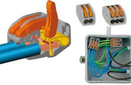
Wago terminals
Wago spring terminal blocks are one of the most popular devices used in connecting wires.

Unlike standard terminal blocks, in Wago docking is carried out not with screws, but with the help of a special mechanism. The device is equipped with a lever that allows you to secure the conductor while maintaining its integrity. Before using Wago, you need to remove the insulating layer. Next, the cores are directed into the block hole.
Note! There are both disposable and reusable pads on the market. Disposable fasteners mean that they can only be used once, and if the wire is replaced, the pads become unusable. Reusable terminals are more expensive, but can be easily removed and then reused for their intended purpose.
Advantages of Wago spring pads:
- You can connect both conductors from the same metal and dissimilar materials.
- It is possible to connect multiple cores (three or more).
- When fixing multi-core conductors, thin wires do not break.
- The pads are small in size.
- Working with pads does not take up extra time, the process is not labor-intensive.
- The fastening is of high quality.
- The block has a hole for an indicator screwdriver to monitor the functioning of the electrical network.
Wago has one drawback - the high cost of products.
Self-insulating clips (PPE)
A self-insulating clip (or connecting insulating clip) is a plastic cap, inside of which there is a special spring for fixing the wire.

The advantages of PPE include the following characteristics:
- Low cost.
- The products are made from non-flammable plastic, therefore, there is no danger of spontaneous combustion of electrical wiring at the junction point.
- Easy installation.
- A wide variety of color shades, which allows you to color-code phase, neutral and ground.
The disadvantages of PPE include:
- low fastening and insulating qualities;
- impossibility of using for connecting aluminum and copper conductors.
Crimping with sleeves
Connecting wires in a junction box using sleeves is considered a method that ensures high quality connections. The essence of the technique is to place the stripped cores in a special tube (sleeve), which is then subjected to crimping by crimping. Next, the sleeve is treated with insulating material, for which heat-shrinkable tubing or regular insulating tape is used. Wires can be inserted from both ends of the tube, or only from one end. In the first case, the joint will be located in the middle part of the sleeve, but in the second case it is necessary that the total cross-section of the cores is no larger than the cross-section of the sleeve.

Advantages of crimping:
- The connection is of high quality and reliable insulation.
- Affordable prices for sleeves.
Disadvantages of crimping:
- The sleeve cannot be replaced once removed - it is a one-time use attachment.
- The connection will require the use of specialized tools (crimping pliers, pipe cutter).
- Crimping of aluminum and copper wires is possible only with the help of a specially designed sleeve.
- The work is labor intensive.
Soldering
Connection using soldering is considered the highest quality of all possible. Before docking, you need to thoroughly clean the conductors. Next, the bare ends are treated with molten solder, after which the wires are immersed in the bath. When the conductors have cooled, insulating material (cambric or electrical tape) is applied to them.
Note! The cooling process should not take place in cold weather, since as a result of too rapid cooling, the material will become covered with microcracks, which will greatly deteriorate the quality of fixation of the conductors.
As already mentioned, the main advantage of soldering is the unsurpassed quality of the connection.
Disadvantages of the technique:
- A specialized tool is required, as well as skills to handle it.
- The work requires significant labor costs.
- The connection is permanent, that is, disposable.
- There are restrictions on the use of soldering, which are detailed in the PUE.
- Over time, soldering resistance increases, which is reflected in the form of voltage loss and electrical conductivity.
Thus, despite the reliability of the connection, specialists rarely turn to soldering.

Welding is sometimes used instead of soldering. The essence of this method is the same as in the case of soldering. The only difference is the need for different skills, namely the ability to work with a welding machine.
Twist
Connecting wires in a junction box using the most primitive method - twisting - is not used so often due to significant limitations: poor quality of fastening and the impossibility of joining aluminum and copper conductors. However, twisting is still sometimes found, since it is attractive due to its ease of implementation, as well as the lack of financial costs. Most often, twisting is used when laying temporary electrical wiring. It is recommended to use cambrics as an insulating material.
Note! Twisting is unacceptable in rooms with high humidity, as well as in wooden buildings.
Walnut clamp
The “nut” is a cable clamp with two plates and four bolts in the corners. Before connecting, the insulation is removed from the wires. Next, the conductors are fixed in the plate and covered with a carbolite shell.

Benefits of "nut":
- Low costs.
- Installing the “nut” is not very difficult.
- It is possible to connect dissimilar materials (aluminum and copper).
- High quality insulation.
Disadvantages of this method:
- The fasteners weaken over time and need to be tightened regularly.
- The “nut” is not the best method of mounting in a distribution box due to the excessive dimensions of the connection.
Bolted connection
Bolting is a very simple but effective way of connecting conductors to each other. To complete the job, you only need a bolt, three washers and a nut. The diagram for connecting the wires in the junction box using a bolt is shown in the picture below.

A washer is threaded onto the bolt thread. Next, the core is wound (the insulation must first be removed). After this, the thread is laid with a second washer and another core. At the end, a third washer is placed, which is pressed with a nut. The connection must be covered with insulating material.
The bolted connection has the following advantages:
- low cost;
- ease of implementation;
- the ability to connect products made of copper and aluminum.
Disadvantages of connecting conductors with bolts:
- Insufficient quality of fixation.
- You will need a lot of insulating material.
- The bolt is too large and may not fit into the junction box.
Solving other problems
The connection of stranded wires has a number of features.
Connecting many wires
Options for connecting two contacts were discussed above. If we are talking about connecting multiple contacts, it is recommended to choose among the following options (in order of priority - from the best method to the worst):
- Wago terminal blocks;
- crimping with sleeves;
- rations;
- twists;
- insulating tape.

The rules for docking using the indicated methods, as well as their advantages and disadvantages, are discussed above.
Docking of cores with different sections
To combine cores of unequal cross-sections in a junction box, you will need Wago terminal blocks, although you can get by with standard terminal blocks - the latter option will be cheaper. In this case, it is necessary to secure the cores tightly using a screw or lever.
Note! If the wires not only have different sections, but are also made of different metals, you will need special pads, inside of which there is a special composition to prevent oxidative processes. Similar pads are available in the Wago range.
Cores with different sections can also be secured by soldering.
Joining of stranded and single-core conductors
The combination of conductors with one and multiple cores is carried out in the same way as all others. In this regard, you can choose any of the above methods, but the highest priority is soldering or terminals (preferably Wago).
Procedure for carrying out work in land and water
It is not so rare that there is a need to lay electrical wiring underground or underwater. Let us briefly dwell on the features of performing electrical installation work under these conditions.
Wires can be laid in water, for example, when installing a submersible pump. In this case, soldering of the wire ends is necessary. Next, the connection is treated with insulating material (hot glue), and heat shrink is put on top. If the technology is followed, the joint will be very reliable and safe. However, if you are careless, it will end in a short circuit.
Wiring in the ground is protected in the same way as described above, however, to obtain a secure connection, a more advanced technique can be used. The ends of the cable should be pressed with a terminal block, and the sealed junction box should be filled with silicone. It is recommended to place the underground pipeline in a durable box or pipe to prevent acts of pestilence by rodents. Damaged cable ends are best joined using couplings.
Basic wiring diagrams
Above we talked in some detail about how to connect the wires in the junction box. However, the work is not limited to connecting wires in the junction box. You also need to connect the wires to sockets and switches.
Connecting sockets
A group of sockets is usually separated into an independent line. There are three wires in the box, each of which has a color specific to its purpose. Brown is usually live, blue is neutral, and green/yellow is ground. In some cases other colors are used. For example, phase is red, zero is blue, ground is green.
Before laying, the wires are laid out to their full length and trimmed so that they are the same length. It is necessary to have 10-12 centimeters of reserve - just in case. The connection of conductors is carried out using one of the methods described above.
If only a pair of wires is involved (where grounding is not used), then we are talking about neutral and phase. If the conductors are the same color, you first need to find the phase using a multimeter. For convenience, it is better to mark the phase wire with electrical tape or a marker.
Connecting a one-button switch
In the case of a switch, there are also three groups, but the connection is made a little differently. There are three inputs: from the junction box or electrical panel, from the lighting fixture, from the switch. The phase wire is connected to the switch button. From the output of the switch the wire is directed to the lamp. In this case, the lighting device will only work when the switch contacts are closed.
Connecting a two-button switch
In two-key switches, the circuit is somewhat more complex. A three-wire cable must go to the switch serving two groups of lighting fixtures (if grounding is not used). One conductor is assigned to the common contact of the switch, the remaining two are directed to the output of the buttons. The phase is combined with the common contact of the switch. The neutral wires from the input and two groups of lighting fixtures are connected. Phase wires from lighting fixtures and two conductors from the switch are combined in pairs: one from the switch to the phase of one of the lamps, the second from the switch to the other lamp.