Operating instructions for multimeter dt9205a. Multimeter DT9205A, but this is not the one that I ruined then
And today we will talk about how and what can be measured with a digital multimeter. For clarity, I will use the DT9205A model. But all of the above can be applied to most similar models, since they are very similar and differ only in some functions.
So, the DT9205A multimeter is designed to measure:
— direct and alternating voltage;
— direct and alternating current;
— resistance;
— capacitor capacities;
— continuity of diodes and transistors.
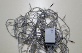
On the front panel we see a display. The maximum value that it can display is 1999. Below the display there are two buttons, one for turning on/off (ON/OFF), and the second for fixing readings (HOLD). It is also unimportant that the multimeter has an auto-off function, i.e. If it is not used for a long time, it turns off on its own. Next comes the circular range switch, which we will look at below. Under the switch there are sockets for measuring capacitance and transistors. Well, at the very bottom there are 4 connectors for connecting probes.
There is a fuse inside the device, which often blows if the current measurement range is incorrectly selected. Power is supplied from a 9V battery, commonly referred to as a “crown”.
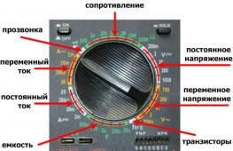
Let us now consider everything in more detail. I think it’s only worth mentioning the on/off and recording buttons, since everything is obvious with them. Next, ranges. They come in both groups and singles. For ease of perception, they are painted in different colors. Let's look at them sequentially, moving clockwise.
— The first group is resistance, it includes subranges for measuring Ohm (Ohms), kOhm (kiloOhms) and Mohm (megaOhms) and is indicated by the Ω icon.
— The next group is constant tension. Subranges allow you to measure mV (milliVolts) and V (Volts). Indicated by the V- icon.
- Directly behind her is a group of alternating voltage. Here everything is the same as in the previous group, you can measure mV (milliVolts) and V (Volts), BUT already alternating voltage. Indicated by the symbol V~.
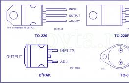
- The so-called single range - hFE (I haven’t found how to read it correctly), is intended for measuring the current gain for bipolar transistors. And directly below it is a socket where transistors are inserted.
- Behind him again is a group - a container. It can be used to measure capacitors. Subranges allow you to measure both nF (nanoFarads) and μF (microFarads). The measurement socket is located just below. Indicated by the F icon.
— Next, the group is DC. Subranges include mA (milliamps) and A (amps). Indicated by the symbol A-.
— The next group is similar to the previous one, but is used to measure alternating current. The subranges are the same. They are indicated by the symbol A~.
— And the last range is dialing. It is used to check the integrity of circuits (it beeps) and check diodes.

The next thing we need to look at is the bottom row of nests. The sockets work in pairs and are connected according to the figure. Red arrow - red probe, black - black.

As for the measurements themselves, everything is simple. We find out what value we need to measure. Next, we set the switch to the maximum possible value (or a smaller one, provided that the maximum number of the subrange is greater than the value being measured), if necessary, rearrange the probes, and take measurements. If the measurement value is too small, select a smaller subrange. For example, we measure a regular battery with a voltage of 1.5 Volts. Having played it safe, we chose a subrange with a limit of 20 Volts; according to the readings, it is obvious that you can choose a smaller subrange, i.e. 2 Volts. This will make the readings more accurate. Sometimes it happens that in the process of measuring current in the 200 mA subrange, the current value turns out to be greater, as a result of which the fuse blows. After which, current measurement becomes impossible until the fuse is replaced.
Well, that seems to be all I wanted to say about measurements with a multimeter. Of course, there are many other models on the market, but they are all similar, so I think there is no point in describing them all, since they are all similar both in functionality and interface.
For proper handling digital multimeter you need to know a number of rules regarding its preparation and direct work with it. Preparation of the device means the procedure for selecting the mode and measurement limit of the controlled variable, as well as the correct connection of the connecting wires to its terminals and to the circuit section.
We will consider all this information using the example of working with multimeters DT 9205A and DT 9208A, slightly different from conventional models by the presence of a number of additional functions.
Measured parameters
Let's start with the fact that through these pr.
in “F”, frequency “Hz” (in a small range), as well as the gain of transistors “hFE” of both conductivities. Separate functions in them provide the ability to measure the temperature of a local object and fix logical levels when working with microcircuits.
All specified measurement modes are selected through a central radial-type switch, the pointer of which is moved to the desired sector before measurement. Within the boundaries of each sector, it is possible to select a measurement limit determined by the approximate value of the desired parameter.
Checking with a multimeter
Let us remind you that the device includes three cords, two of which allow you to create closed measuring chains. Using a third set of leads equipped with a Type K thermocouple, you can measure the temperature at a local point in the circuit or object being monitored. Let us consider the order of measurement behavior for each of the listed parameters.
AND.
a measured resistor on each of its sides (photo on the right);
— at the same time, readings are read from the indicator board corresponding to the resistance value of the element in units of the selected limit (Ohm, Kom or Mohm).

For checks circuit integrity, with the same connection of the probes, the switch is switched to the mode marked with diode and sound signal symbols. When the ends of the probe touch a working (short-circuited) circuit, a tone should be heard.
For checks
diodes with the same probes carry out a double measurement, realized by changing the polarity. When connected directly to a working diode, the indicator should display a voltage drop across its junction, and when connected in the opposite direction, there should be an open circuit (infinity).
in units of the selected limit (mV or Volts).
Note: For DC voltage there is a microvolt limit.
The frequency of the alternating signal is measured with the same probes turned on, the measuring ends of which are connected to the section of the circuit being examined.

Taking current and other readings
To measure current, the end connected to the universal terminal “VΩ” should be moved to the socket marked “mA” (the common black measuring cord remains in the same position). Let me also remind you that to take current readings, the ends of the probes must be included in a break in the chain being measured. In this case, the required measurement limit of up to 200 mA is selected based on the expected current value in it.
To determine current indicators of larger values (up to 20 Amperes), the measuring cord is connected to a socket marked “20A”, equipped with a special shunt.
Additional Information: If it is necessary to measure the capacitance of a capacitor, the arrangement of the cords is selected in the same way as when determining current values within the range of up to 200 mA.
When measuring the parameters of transistors, they are placed in a special block with two lines of 4 sockets, designed for different pinouts.
One of the lines is intended for semiconductor devices of the “n-p-n” type, and the second is for “p-n-p” transistors.
To determine logical levels when working with microcircuits, the position of the probes on the device is standard. When the logical level is high, the indicator displays an arrow pointing up, and when it is low, the arrow points down.
In conclusion, I will note two more possibilities from the functional set of devices of the type under consideration. These are: automatic shutdown of the display during a long pause in measurements “AUTO OFF” and the function of storing the last reading “HOLD”. The first of them is very convenient in terms of saving on not very cheap “Krona” type batteries, and its name itself speaks about the advantages of the second.
Thank you all for your attention! I'm also waiting for you on the channel "Telemaster" on YouTube and in groups "Samodelkin" VKontakte and "Teleworkshop" in Odnoklassniki!
viktorkorolev.ru
In this review I will try to describe these two extraordinary devices, intended mainly for home or amateur radio equipment. So kindly provided by the TomTop store.
There will be photos. There will be measurements. And also a burnt probe, which was inserted in parallel into 220V without load, in current measurement mode :)
After my cheap tester, the dipstick broke in the most unpleasant place. It was decided to order a new one, and not one, but two, so that both voltage and current could be measured at once.
I didn’t want to spend too much money and decided to order these multimeters:
Multimeter DT830B - AC/DC Professional Electric Digital Multimeter Tester Checker
Multimeter DT9205A - AC/DC LCD Digital Multi-meter Volt Ohm Amp Tester Checker
They arrived very similar to them, although the markings of the models are the same.
Here's a video of them unboxing:
http://youtu.be/lJ-Jjp4C1A8
Let's see what they are capable of.
I'll start with the small one.
These are the characteristics compiled for it in the store: 
Here's what it says on the box: 

Came in this kit (box + tester + probes, they decided not to include instructions): 
It can measure direct and alternating voltages, direct current, resistance, transistor parameters (I have never measured them), and diode continuity, but unfortunately there is no speaker.
Here is a photo of the front panel with a circular lever: 
But his probes are cheap, the wire is thin, perhaps this saved me :) 

Their resistance is 1.5 Ohm: 
I decided to start by measuring DC voltage; I only had a computer at hand. power supply, I checked everything on it (without load).
12V (showed 13.22V): 
5V (showed 5.01V): 
3.3V (showed 3.37V): 
Measuring the resistance of resistors.
10Ω ± 5% (showed 10.9Ω): 
91Ohm (showed 99.3Ohm): 
300Ω ± 5% (showed 300Ω): 
Let's measure direct current (measurements were carried out on a Convoy S3 flashlight, which can operate in 3 modes and the current consumption in them is 0.1A, 0.8A, 2.1A)
1 mode: 
2 mode: 
Mode 3 (I was pleasantly surprised that with such probes I was able to see a current of 2 A): 
And now I decided to measure the voltage in the network, set the desired limit with the lever, but forgot to switch the positive probe to the desired socket, and so I plugged it into the socket :) 
As a result, sparks, a little smoke, and of course the smell of burnt plastic, and... a torn dipstick.
Well, it's lucky that they have such a thin wire. By the way, he decided to get it out of everything: 
The other probe also suffered a little, the end melted: 
Well, let's see what's inside.
This is what the back wall tells us (note there is a fuse 😉): 
Here are its insides: 
Hmm... Someone forgot to solder the fuse, and I suspect that it’s not just him, but oh well, it doesn’t happen to anyone :) 
As always, huge drops of solder and unwashed flux: 

I'll put it back together and put it away.
Let's move on to the second tester. To DT9205A. How is it different from the first one? Why pay about 8 bucks more?
It can automatically turn off after 15 minutes of inactivity, it can beep, it can blink with an LED, it can measure capacity, direct current up to 20A (wouldn’t risk it), temperature (but no idea how, for some reason they didn’t put probes for this)
Here are its characteristics posted on the website: 
Here's what the box tells us: 

But the most interesting thing is inside the box. Find 10 differences. Photo on the box: 
Photo of the device: 

And here are his probes (also not very good): 
There is already some paper here that looks like instructions: 

I want to turn it on. Doesn't turn on. It's clear. Let's see if there is a battery. Hmm... Savings again from expensive manufacturers. 
While I was twisting and turning it in my hands, I was confused by some extraneous sound inside the device, as if something small was dangling in it, it cracked again, and one radio element fell out of the battery compartment (like a diode): 
I didn’t like it, so I decided to take it apart and at the same time take a photo of the insides. Here he is without rubber galoshes: 
And here's the breakdown: 
No matter how I tried to find where this diode could have fallen off, I couldn’t find it. But the most interesting thing is that this is not all, the extraneous sound remains. Okay, let's take a look further. And this is what I found in the switch lever: 

Photo of the board: 

As always, not without its jambs. Solder, flux... 


Some scratches: 
Another interesting point confused me, it was not really planned to do this, part SMD part of ordinary resistors: 
Never mind, let's put it back together. Let's check how it works.
Continuity of circuits/diodes. The speaker beeps, the LED lights up: 
Probe resistance (1.1 ohm): 
Measuring DC voltage from a computer power supply without load.
12V (showed 13V): 
5V (showed 4.93V): 
Well, for some reason I wanted to measure the charged Li-ion battery (showed 4.1V): 
Resistance. 10Ω ± 5% (showed 9.9Ω): 
68KOhm 
Current (all on the same flashlight). Everything is bad here, apparently the probes took their toll (or I measured something wrong)
Photo with three modes: 


I wanted to measure the capacity, but somehow I didn’t understand how to measure it. Anyway.
That's all.
If you need a cheap, unpretentious multimeter, without much emphasis on accuracy, then you can take it. Taking into account the fact that if you suddenly burn it due to inexperience or carelessness, then you won’t mind throwing it away and buying a new one.
mysku.ru
Types of device
All multimeters or multitesters are divided into two large subgroups:
- Analog. They are made in the form of a scale and arrow. When working with such a device, it is necessary to take into account the indicators of the established limit, which a professional electrician is well versed in.
- Digital. Modern options that show the value on a digital display, with a parameter switch knob or push-button control. Advanced versions have functions for reading parameters of capacitor capacitance, frequency and pulse duration.
Important! In conditions of strong radio interference and signal noise, only the analog version is used to obtain accurate values.
How to use an analog multitester
The analog tester uses a general indicator to display the measured readings. On the scale behind the arrow there are several divisions: for volts, amperes and ohms.

The tester works on the principle of converting measured data into electricity, which creates a magnetic field, which in turn moves the needle. In this case, switching of input connectors and control of operating modes of the circuit is realized using a multifunction switch with buttons. A similar “handle” is also provided on digital versions.
Instructions for use of the analog tester
Let's look at how to use a dial multimeter and set it up to work:
- Check the batteries using a special mode.
- Perform a zero calibration. For these purposes, there is a tuning resistor, the handle of which is located on the front panel. It is also used when moving from one range to another. For example, changing the position from 10 Ohm to 10 Mohm, the spread is up to 25% of the scale length.
- Set AC or DC voltage. (The device contains a diode rectifier, since the magnetic head of the dial indicator functions only with direct current).
- Activate the shunt, which helps measure resistance over wide ranges on the sensing pointer mechanism.
- To select a measurement value, you must connect the device to the correct connectors, and you must observe the switching. If you do not follow all the rules for connecting to each section of the circuit where the current strength is different, the multimeter will fail.
- The connection between the device and the circuit is carried out using probes or clamps similar to crocodiles, which are named accordingly.
Important! During operation, do not touch exposed contacts with bare hands, even if the voltage seems safe.
Features of digital multimeters
The operation of the device is based on an analog-to-digital converter, where the incoming analog signal is converted into a digital code for further processing by a controller chip. To read parameters, you need to connect wires (probes) to the circuit or its components. The black probe is negative or general, the red probe is positive.

To understand how to use a multimeter correctly, familiarize yourself with the main symbols on the panel:
- off - the device is turned off;
- avc - alternating voltage indicator;
- dvc - constant voltage;
- dca - direct current;
- Ω - resistance.
Any modern multimeter has three connectors for connecting wires. It is necessary to connect the wires correctly so as not to damage the device and correctly read the data:
- the black wire is connected only to the COM input;
- if necessary, measure current up to 200 mA or resistance, plug the red wire into the “VΩmA” connector;
- if the current is more than 200 mA, then the red cord is connected to “10ADC”.
To remove individual parameters, you use your own connection and adjustment diagram for the device. To fully understand all the features of the tester, below is a step-by-step instruction in the style of “how to use a multimeter for dummies.”
Detecting a short circuit in a circuit
The multitester is used in different ways for different purposes. Let's look at an example of how to use the DT838 multimeter to detect a short circuit (hereinafter referred to as a short circuit) in a circuit. This is a universal model that is often used by radio amateurs at home. It runs on a 9 V Krona battery. In addition to standard functions, this device has sound signals for continuity and the ability to measure temperature.

To determine the presence of a short circuit, follow the instructions:

So quickly and easily you will find out about the presence of a short circuit.
How is direct current measured?
Let's look at how to measure the DC current in a battery using the DT182 multimeter model as an example. This is a compact device that is used in everyday life, with a measurement speed of 2-3 times per second. They can also test the circuit for short circuits and perform all other basic measurements.

To find out whether the battery is charged or not, do the following:
- Turn on the DT182 multimeter and install the probes in the correct position (as in the previous example for determining a short circuit).
- Set the “knob” to the maximum value of 500 V.
- Attach the free end of the black probe to the non-insulated part of the battery.
- Place the red probe on the measurement point, for example, on the “+” battery.
- If during the measurement process the display shows numbers from 12 to 14.6 V, then the battery is charged.
Tip: to increase the measurement accuracy, you can set the switch to 20 V, but not lower than this value.
Checking the outlet or measuring AC voltage
In addition to determining the battery charge or the presence of a short circuit, a multimeter is often used to check the functionality of the outlet. Let's consider this action using the compact tester model DT9205A as an example. Its features are high measurement accuracy, but the lack of temperature measurement functions and there is no thermocouple.

To check the voltage at an outlet, do the following with your DT9205A multimeter:
- Place the probes in the corresponding sockets “COM” and “VΩmA”, and turn the control knob to ACV (750 V).
- Plug the probes into the socket one at a time, and it doesn’t matter which one you insert where.
- If a value within 200–220 V appears on the screen, this is considered a good indicator.
This method is used to check household sockets for their functionality. Even a non-professional can master this technique with a DT9205A digital multimeter in his hands.
Important! Each device comes with detailed operating instructions, where you can find answers to all your questions.
Features of checking the thermocouple
A thermocouple is a sensor consisting of two dissimilar conductors having several contacts with each other. It works on the principle of voltage generation by these conductors due to temperature changes in any part of the sensor.

So, how to check a thermocouple with a tester if the button on the gas boiler box does not lock during operation. To identify such a malfunction, do the following:
- Turn off the boiler completely, cutting off the supply of gas and electricity. This is necessary for safe operation.
- The thermocouple is located between the temperature sensor and the nut with which it is attached to the valve.
- It is necessary to remove the thermocouple by unscrewing the nut.
- Heat the sensor over an open, constant flame, for example, over a burner that is on. At the same time, keep the device at a distance of 10 mm from the flame. Wear gloves first to avoid getting burned.
- Set your multimeter to mV. Then, attach one probe to the thermocouple body, the other to the output contact.
- Within a minute after heating, the device will detect the presence of voltage. The tester screen should display a number from 18 to 25 mV, which indicates that the thermocouple is working.
It is not difficult to understand how to use a multimeter (tester) correctly; the main thing is to set the necessary parameters on the digital device and connect the probes correctly. You should also pay special attention to choosing a multitester and follow some recommendations:

- Most Chinese multimeters, including the popular DT9205A model, have fragile probes. They can be strengthened using cambrics or holding tubes. They will ensure that there are no kinks near the clamps and will extend the service life of the device.
- You need to start measuring from larger values to smaller ones, this will avoid blowing the fuse inside the multimeter.
- If the device does not turn on, the cause may be a dead battery. You can buy it in any specialized store, calling the subtype “Crown”.
- You can rotate the switch in any direction if you did not have time to connect the probes to the circuit or device being tested.
Learn to use a multimeter and determine short circuits, measure DC and AC current readings, as well as other parameters in everyday life will become much easier.
profazu.ru
Surely you know, even if you are a beginner, that in every laboratory of a radio amateur, even not the most avid one, there should be a measuring device such as a multimeter. When you bought a multimeter, the first question is “How to use a multimeter?” How not to burn such a, sometimes expensive, device. This is my task right now, to tell you as clearly and clearly as possible how to master using a multimeter. Using my example, I will talk about the DT 9205A multimeter. This multimeter is not very different from cheaper devices such as DT832, but for a small overpayment I got several useful functions, which I will talk about a little later
I apologize in advance for the photo quality
Well, let's get started. All functions of the multimeter are divided into limits for more accurate calculation of certain parameters. Therefore, before measuring anything, set the limit as high as possible, so as not to inadvertently burn the multimeter
1.
Let's start with resistance. Probably one of the most frequently used functions for me. Especially when you need to select a couple of resistors of the same resistance. There are only 7 limits on my multimeter, but they are enough for me, although there are fewer and more. The first is the limit from 0 to 200 Ohm, the second - from 200 Ohm to 2 kOhm, the third from 2 kOhm to 20 kOhm, the fourth - from 20 kOhm to 200 kOhm, the fifth - from 200 kOhm to 2 MOhm, the sixth - from 2 MOhm to 20 MOhm, the seventh - from 20MΩ to 200MΩ. There are so many limits, how do you choose the right one? We take a resistance, say 270 Ohm, or its resistance will be written on it, in the example as with MLT, or it will be a color marking of the resistor. We set the limit a little higher than the nominal value, this will be the limit on which 2 kOhm is written, and we measure with probes on the legs of the resistor, insert the black probe where it says COM, and the red one where the Omega icon is. It showed us a resistance of 268 Ohms. This means that the multimeter is not lying, but it is worth considering that the probes themselves have their own resistance, for example 1.5 Ohm, which means the resistance is somewhere around 266 Ohm. To be honest, I have never used limits above 2 MOhm. Although there's still more to come
2. Next on our list will be ACV, which is a measurement of direct voltage. There are also several limits, or rather 5. The first limit is from 0V to 200mV, the second is 200mV to 2V, the third is 2V to 20V, the fourth is 20V to 200V, the fifth is 200V to 1000V. To measure the voltage we need, insert the black probe into COM, the red one into connector V. We set the limit to 1000V and measure the voltage. Let's say, like me, it showed us only 3B. This means we set the limit to 20V and measure the exact voltage. My battery is 3.26V. We set the upper limit so as not to accidentally burn the multimeter
3. Next we will consider ACV-alternating voltage. There are also 5 limits, the first limit is from 0V to 200mV, the second is 200mV to 2V, the third is 2V to 20V, the fourth is 20V to 200V, the fifth is 200V to 750V. For example, let’s measure the voltage in a 220V network. We set the limit to 750V, the black probes are in COM, the red probes are in V. And in the socket. Showed 220V. To be honest, we have good voltage, but sometimes it jumps to 240V.
4. The next quite useful thing is the hFE transistor gain meter. There are 8 holes at the bottom. Four each for PNP and NPN transistors. We insert the desired transistor and find out the hFE of the transistor. Useful, especially when you need to find a couple of identical transistors when assembling transistor amplifiers
5. An interesting function is measuring capacitance F. We set an approximate limit, there are 5 of them in total. The first limit is from 0nF to 2nF, the second is 2nF to 20nF, the third is 20nF to 200nF, the fourth is 200nF to 2mF, the fifth is 2mF to 200mF. We insert any ceramic, electrolytic capacitor into the CX connectors and find out its capacity. It’s good to check containers when making generators, replacing containers in equipment, etc.
6. Let us now consider the current consumption meter. An ammeter, designated A. Let's consider it immediately for both alternating and direct voltage. Each has four limits, the first from 0mA to 2mA, the second from 2mA to 20mA, the third from 20mA to 200mA. It is convenient to measure small consumers, such as LEDs and similar small items. To measure, we set the limit, the red probe is in mA, the black probe is in COM and we measure by connecting it in series to the consuming device. The main thing is not to confuse the DC and AC current meter and do not exceed the measurement of more than 200mA, the fuse, of course, will save you, but you shouldn’t take the risk. Better read about the next limit. The fourth is special from 0mA to 20A. It has a separate 20A connector. Everything is measured the same way, consistently to the consumer.
7. And the last function on my multimeter is continuity. Quite a useful thing when you can’t look at a multimeter. We simply clamp the two edges of the conductor with screws and if its resistance does not exceed 40 Ohms, a ringing will be heard. A very convenient thing for testing broken diodes
And a couple more useful functions on the DT 9205A:
A Automatic shutdown if you do not use the multimeter for a while. I like it because I often forget to turn off the multimeter, and it runs for a very long time and the battery runs out
IN Another useful feature is the HOLD reading memory. No matter what to record every time, press the button and voila
T Some multimeters also have a square-wave frequency generator function. A useful thing for checking the stages of an AF amplifier assembled on transistors. It helped me more than once, but it’s not on the DT 9205A, but it was on the DT832
Finally, I will say that multimeters are all similar, only slightly different in functionality
That's all, thank you for your attention, understanding and patience

This beautiful specimen will be yours for only 322 rubles; the set includes magnificent burrs with thin needles that fit perfectly in your hands. The goods will be delivered in just 3-4 weeks
After purchasing the Multimeter Digital DT9205A universal device, users often wonder how to configure it correctly, select operating ranges for more accurate results, and how to use the multimeter so that it works without failures, breakdowns and for a long time.
Let's give a brief overview of the multimeter with a description of all its capabilities and settings.
Short review
The digital multimeter is designed to measure current, DC, AC voltage, resistance, and capacitance of capacitors.
With its help, the frequency gain of the transistor is determined, diode testing is carried out and the circuit is tested with an audio signal.
The DT9205A multimeter is a reliable, compact, digital tester. This is an excellent assistant in amateur radio engineering, industry, and agriculture.
A digital multimeter calculates the reliability and performance of any household appliance and accurately assesses the safety of using switches, sockets, and electrical equipment.
It can be used to repair car electrical circuits, repair radio equipment, power supplies, and in laboratory research.
The digital multimeter is multifunctional and portable. Power is supplied by a battery. Thanks to the small size of the device, its transportation and storage are easy.
It includes an analog-to-digital converter, which is made using CMOS (metal-oxide-semiconductor) technology with functions such as automatic zero calibration, negative polarity indication. The circuit has overload and overvoltage protection in all ranges.
 Good performance is ensured by a 30-position rotary mode switch.
The rubberized case protects the device from external influences and accidental falls.
Reviews from users who purchased this device are only positive. The multimeter is simple and easy to use. Its cost is low.
The only drawback of the model is that the tester does not support temperature measurement modes; there is no thermoelectric converter or thermocouple.
The device kit includes:
- tester;
- probes;
- Krona battery 9 V;
- management.
Features and Functions
 Main characteristics and functions of the DT9205A multimeter:
- Basic DC accuracy is ±0.5%.
- Capacitance measurement - 1 pF - 20 µF.
- Resistance measurement - 0.1 Ohm - 200 MOhm.
- Indication of incorrect testing.
- The maximum reading on the LCD screen is 1999 (3 1/2 digits).
- The maximum COM input voltage is 50 V (DC).
- The operating principle is an ADC with a 2-loop integrator.
- Test speed is 3 counts per second.
- The temperature range for precise measurement is 18-28°C.
- Operating temperature range: 0-40°C.
- Storage temperature: 10-50°C.
- Ability to adjust screen tilt.
- Automatic shutdown of the device.
- Convenient stand.
- Dimensions - 186x86x41 mm.
- Weight - 318 g.
- Brand - Digital.
- Country of origin: China.
Basic Multimeter Measurements
 To measure DC or AC voltage, you must follow the instructions:
- Connect the black probe to the COM input jack, the red one to the V/Ω input jack.
- Turn the mode switch to the desired DCV position.
- Attach the probes to the device being tested. The voltage parameters and polarity will be displayed on the screen.
When measuring current indicators, you must:
- Connect the black probe to the COM jack, the red probe to jack A (maximum 200 mA) or 20 A input (maximum 20 A, 10 seconds).
- Turn the switch to the DCA position.
- Connect the probes in series to the device being measured.
- Current indicators and polarity will be displayed on the screen.
 In the process of measuring these parameters, it is necessary to take into account the following factors:
- if the voltage being tested is unknown, the range switch button is set to the maximum position;
- when the overload and overvoltage symbol appears on the indicator, switch 1 is turned to a larger operating range;
- do not apply more than 1000 V for direct voltage and 700 V for alternating voltage to the input, so as not to damage the circuit diagram of the device;
- when working with high voltages, do not touch the circuit;
- The measurement time should not be more than 15 seconds when connected to a 20 A socket, otherwise the device circuit will fail because there is no fuse.
 Many novice radio amateurs do not know how to use a multimeter to measure resistance.
To solve this issue, you need a tester and resistance to be tested. Before carrying out work, the circuit must be de-energized.
- Connect the black probe to the COM input jack, the red one to the V/Ω jack (red probe polarity +).
- Turn the switch to the Ω position, connect the probes to the circuit being tested.
Operating notes to consider when testing resistance:

To measure capacitance, set the mode switch to position F, discharge the capacitor by short-circuiting its terminals, and connect it to the input jack Cx, observing polarity.
The results will be shown on the screen. During operation, take into account that external voltage or a charged capacitor cannot be connected.
 When determining the direction of the diode current, connect the probes to the COM, V/Ω sockets on the multimeter panel in the same way. The mode switch is set to the diode testing position, the probe is connected to the diode.
The forward voltage drop will be displayed on the screen when forward current is flowing, measured in millivolts. If the current flows backward, the overvoltage symbol 1 appears. Test current is 1.5 mA.
Attach probes to 2 points of the circuit being tested. When the resistance is less than 70 ohms, the built-in speaker emits a sound signal. This phenomenon is called chain ringing.
Measuring the frequency gain of a transistor is performed as follows:
- The rotary switch is set to the hFE position.
- Determine the type of transistor (NPN or PNP) and the pinout of its terminals.
- Connect the leads correctly to the input sockets of the multimeter.
- With a base current of 10 μA and a collector-emitter voltage of about 3 V, the indicator will show the approximate value of the hFE coefficient.
By following these instructions, you can ensure the operation of the multimeter for many years. With proper configuration and proper connection to devices, the device will work without breakdowns, failures and show accurate results.
I ordered this multimeter for a friend of mine (we work together). I will compare it with the sample again. The device is still a measuring device. The device is the simplest, but it can do a lot.This is a device from a “group purchase”. I buy, having collected at least $40 worth of goods for a free track.
The parcel was sent with delivery by SDEK.
This is not the first time I have received parcels through them. True, I receive it myself, without a courier. The courier works on weekdays, and I also work on weekdays.
I wrote about the nuances of delivery in a previous review. The parcel arrived in a green branded package, which means it was opened (most likely at customs). They stole the adapter :(
There was a delivery slip inside. From him I learned about this joy.
The packaging is standard - (inside) a paper “pimpled” bag with an address. There's a box in it. 
The cardboard box is exactly for this model. 
The kit included the device, warranty card, instructions and probes. 
There are two instructions: one in English, the other in Chinese. 
The instructions are not very voluminous (nine pages). 
A better scan of the instructions can be found here:
- instructions.
The probes are cheap. Length 70cm from tip to tip. Photo with analysis.

The device is packaged in a bag. 
Medium sized multimeter. 
It fits comfortably in the hand. 
Weighed it. 221g. with battery. It came with the kit and was already inside the device. 
The stand is “free” and reclines about 80 degrees. 
All inscriptions printed on the device have clear outlines, are not blurred anywhere, and are easy to read.

Display capacity: 2000 counts floating point.
Powered by a 9V Krona battery. The battery compartment is closed with a lid using a self-tapping screw.

The battery is tight and difficult to remove.
The “silicone” case (with a smell) can be removed without difficulty. 
The contrast of the numbers is a solid four, can be compared with HYELEC. 
The display is the simplest. Shows only the digit capacity of the measured values.
The probes are also the simplest, but I have seen worse. 
There is no analogue scale.
Auto power off.
If no operation is performed on the device using the rotary switch or buttons, then after 25 minutes it will go into sleep mode without warning and turn off. To revive it, you need to press the on/off button.
There is battery status monitoring.
_______________________________________________________
Let's move on to the analysis.
I unscrew three screws. 
There are 3 tuning elements inside. Whether this is good or bad, I don’t know yet. A conclusion can be made only after determining the accuracy characteristics. They are labeled, it is clear what and why (top left - constant calibration, to the right - capacitance meter calibration, to the right and below - variable calibration). 
Soldering of parts on the main board without any comments. As the “brain” of the “blob” type MS.
You can look at everything in detail. 
I unscrew four more screws. 
The switch is made according to the same principle as in the widely known MASTECH M890 multimeters.
If you look at the reflection, you can see that lubricant has been applied to the contact pads, but not enough, he added.
Indicator without backlight.
I didn’t see the usual fuse for most multimeters. 
But if you take a closer look it’s worth...
For those who often arrange fireworks, this is of course a minus. But in general, it’s not worth firing it (even if there is a fuse, it doesn’t always have time).
And yet, what can it (the multimeter) do?
The device under review can measure direct and alternating voltage and current; resistance, capacitance; “ring” the circuit for an open circuit and check the diodes, as well as check the transistors.
The rotary switch is the only control element (not counting the on/off button).
I assemble the device and move on to determining the accuracy characteristics.
All the instruments with which I will determine accuracy are expensive enough to have for personal use.
I’ll check how the variable is measured using B1-9 (installation for testing voltmeters).
This setting allows you to measure the error directly as a percentage. But I won't use this option. I’ll just set the reference voltages and see what it (the multimeter) shows. It's more clear this way.
I set the frequency to 50Hz. For ease of perception, I have summarized all measurements in a table. 
The error is about 2%.
Setting V1-9 allows you to change the frequency of the reference voltage. As a result of testing, I found that the multimeter can measure sinusoidal voltage from 15Hz to 1kHz with high accuracy.
I measured the voltage in the network. On the left are the readings of a standard meter. 
Underestimates by more than 5V.
I will evaluate the constant using a programmable calibrator P320. It's simple. I connect a multimeter to the calibrator and write down what it (the multimeter) shows. I put all the data into a table. 
The multimeter indicator shows only numbers. Therefore, we focus on the switch. The error is about 1.7%.
I will check the DC measurements using the P321 setup. The principle is the same as when measuring voltage. 
I move on to measuring resistance. Resistance stores P4834 and P4002 will help me.
I also compiled all the data into a table. I used non-original probes. 
And here the accuracy is within the same limits.
I will check the accuracy of measuring capacitances using the P5025 magazine. 
The multimeter only measures capacitances up to 200 µF.

I can’t calmly look at errors of more than 1%. With the owner's permission, I turned the calibration resistor to a constant value. It is calibrated first, since it also affects the variable. After that, I measured the voltage in the network. 
The error in measuring the voltage in the network has decreased from 5 to 2 V. With a more careful approach, it can be reduced to 0.5 V. I wrote earlier what exactly to twist.
Alternating current was supplied from an installation for testing electric meters. 
I checked only to the extent possible.
After adjustment, the result improved here too.
Continuity diodes and tweeter are combined.

When dialing, the red LED lights up. There are no brakes. It starts beeping immediately.
At the same time, on open probes there is 3.01V. You can also ring LEDs. 
It's time to move on to the final part. I'll highlight what I liked and didn't like. The point of view is subjective.
Minuses:
As the “brain” of the “blob” type MS.
Lack of analogue scale.
Measures capacitance only up to 200uF.
The indicator does not show the measured values (A, mV, ...).
No display backlight.
Batteries 9V.
The display capacity is 2000 floating point counts.
Pros:
Large contrast LCD display.
Auto power off function. The device will turn off after 24-25 minutes.
There is an on/off button. There is no need to flip the switch when turning off.
Availability of low battery indicator.
The device can be easily calibrated.
Price
And one more thing at the end.
I told about the device that I hold in my hands. Everyone decides for themselves how to properly use the information from my review. I can only guarantee the veracity of my measurements. If something is unclear, ask questions (before you give it to the owner). I hope it helped at least someone.
That's it.
Good luck everyone!
Multimeter DT9205A, but this is not the one that I ruined then. Multimeter dt9205a instructions for use
DIGITAL MULTIMETER DT9205A
USER'S MANUAL
DIGITAL MULTIMETER
1. INTRODUCTION
Multimeters DT9202/DT9205A are designed to measure current, voltage,
resistance, parameters of diodes and transistors. The device is multifunctional
portable, battery powered, convenient for repairing car electrical circuits,
laboratory measurements, etc.
2. DEVICE CAPABILITIES.
* Baseline DC accuracy ±0.5%.
* Capacitance measurement from 1 pF to 20 µF, automatic zeroing.
* Resistance measurement from 0.1 ohm to 200 megohm.
* Indication of an incorrect measurement.
*Maximum display value 1999 (3 1/2 digits)
* Maximum voltage of the “COM” socket is 50 V (DC).
* Accuracy is guaranteed at measurement temperatures of 23ºС±5ºС.
* Temperature range: operating temperature 0ºC - 40ºC
storage temperature -10ºС - 50ºС
*Power: 9V battery.
* If the battery runs out, a symbol appears in the lower left corner of the display
* Size: 186x86x41 mm.
* Weight: approximately 318 g, including battery.
CONSTANT PRESSURE
RANGE ACCURACY RESOLUTION
200 mV 100 µV
2 V ± 0.5% 1 mV
1000 V ± 0.8% 1 V
Input impedance: 10 MΩ for all ranges
Overload protection: 1000 VDC for all ranges. (Except
range 200 mV, here the voltage should not exceed 250 V).
AC VOLTAGE
RANGE ACCURACY RESOLUTION
200 mV ± 1.2% 100 µV
2 V ± 0.8% 1 mV
750 V ± 1.2% 1 V
Input impedance: 10 MΩ for all ranges.
Frequency range: 40Hz to 400Hz (except 200V and 750V range, here
frequency should not exceed 100 Hz)
Overload protection: 750 V rms or 1000 V peak.
D.C
RANGE ACCURACY RESOLUTION
2 mA ± 0.8% 1 µA
20 mA ± 1.2% 10 µA
200 mA 100 µA
20 A ± 2% 10 mA
Overload protection: 0.2A/250V fuse (except 20A range)
Maximum input current: 10 A (20 A for no longer than 10 sec.)
ALTERNATING CURRENT
RANGE ACCURACY RESOLUTION
2mA ± 1% 1 µA
20 mA 10 µA
200 mA ± 1.8% 100 µA
20 A ± 3% 10 mA
Overload protection: 200mA/250V fuse (within 20A fuse range
Frequency range: 40 Hz to 400 Hz.
Maximum input current: 10 A, (20 A for no more than 10 sec.)
Reading: RMS value.
RESISTANCE
RANGE ACCURACY RESOLUTION
200 ohm ± 0.8% 0.1 ohm
2 kΩ ± 0.8% 1 Ω
20 kOhm 10 Ohm
200 kOhm 100 Ohm
2 MΩ 1 kΩ
20 MΩ ± 1% 10 kΩ
200 MΩ ± 5% 100 kΩ
Open circuit voltage 1V.
RANGE ACCURACY RESOLUTION
200 nf ±2. 5% 100 pf
20 µF 10 nf
Measuring frequency: 400 Hz
TESTING DIODES AND “TUNING”
RANGE
-|>|- Constant current ~1mA reverse constant voltage ~3V
o))) Built-in buzzer The voltage gives a signal if the circuit is open:
Resistance
TESTING TRANSISTORS
RANGE DISPLAY CONDITIONS
hFE measurement hFE Base current - for 10 mA type transistors, PNP and NPN, range Uce =
4. OPERATING THE DEVICE.
DC VOLTAGE MEASUREMENT.
measured load. The voltage value and polarity will appear on the display.
Comment:
A. If the order of the measured voltage is not known in advance, place the switch in
greatest range.
b. If “1” appears on the display, turn on the switch
Internal circuit.
d. When measuring high voltages, avoid touching the circuit.
AC VOLTAGE MEASUREMENT.
1. Connect the black probe to the “COM” socket, the red one to the V/W socket.
2. Set the function switch to the required DCV position and connect the probes to
measured load.
Comment:
A. see above a, b, d.
b. ! Do not apply more than 750 V to the input.
MEASUREMENT OF DC AND ALTERNATING CURRENT.
1. Connect the black probe to the “COM” socket, the red one to the “A” socket (maximum 200
mA) or “20A” (maximum - 20 A, 10 sec).
2. Set the function switch to the desired DCA position and connect the probes
in series with the measured load.
The display will show the current value and polarity
Comment:
A. If the order of the measured voltage is not known in advance, put
switch to the highest range.
b. If “1” appears on the display, move the switch to a higher range.
V. When working with a 20A socket, the measurement time should not exceed 15 seconds,
because there is no fuse.
RESISTANCE MEASUREMENT
1. Connect the black probe to the “COM” socket, the red one to the V/W socket. (polarity
red probe “+”.
2. Set the function switch to position W and connect the probes to the measured
resistance.
Comment:
A. If the resistance value exceeds the maximum value for a given
range, “1” will appear on the display, Switch to a wider range. At
When measuring resistances of 1 MΩ and higher, stabilization will require some
time, this is normal for the operation of the device.
b. If the circuit is open, “1” will appear on the display.
V. When measuring the internal resistance of a circuit, make sure that the power
switched off and all capacitors are discharged.
d. When measuring resistance in some devices, they may be
damaged. Below is a table of voltages and currents used in
each range.
d. In the range of 200 MΩ with a short circuit, the display shows
When measuring a resistance of 100 ohms, the display will show “101”
and the last unit should be subtracted, i.e. 101-1=100.
When measuring large resistance values. the resistor should be connected
directly with the V/W socket and the “COM” socket to reduce the influence of interference
RANGE A B C
200 Ohm 0.98 V 0.12 V 0.65 mA
2 kOhm 0.98 V 0.45 V 0.42 mA
20 kOhm 0.98 V 0.64 V 0.09 mA
200 kOhm 0.98 V 0.64 V 0.009 mA
2 MΩ 0.98 V 0.64 V 0.0009 mA
20 MΩ 0.98 V 0.64 V 0.00009 mA
200 MΩ 2.8 V ~ 2.8 V 0.0028 mA
A: open circuit voltage
V: resistance voltage
C: current in milliamps when the input circuit is closed.
CAPACITY MEASUREMENT
Connect the capacitor to the input jacks (not the probes), paying attention to
polarity. The value of the measured capacitance will appear on the display. When it changes
measurement range, non-zero numbers may appear on the display - do not
Please note, this does not affect the accuracy of measurements.
Comment:
The capacitor must be discharged before taking measurements. When measuring
Large capacitance values may cause some delay in appearance
final testimony.
Do not connect external voltage or a charged capacitor (especially
large capacity) to the measuring terminal.
MEASUREMENT OF DIODE PARAMETERS.
1. Connect the black probe to the “COM” socket, the red one to the V/W socket.
2. Place the range switch in the -|>|- position and connect the probes to the diode.
Comment:
When the input circuit is open, 1 appears on the display.
A current of 1 mA flows through the device being measured.
The multimeter measures the forward voltage drop in mV.
“TINKING” THE CHAIN.
1. Connect the black probe to the COM socket, the red one to the V/W socket.
2. Place the range switch in position o))) and connect the probes to
measured resistance.
3. Built-in buzzer will sound when the resistance value is less than 30 ohms.
Comment:
A. If the input circuit is open, “1” will appear on the display.
b. In case of incorrect operation of the device, you will hear a warning sound.
MEASUREMENT OF hFE TRANSISTORS.
1. Set the function switch to hFE.
2. Determine the transistor type (NPN, PNP) and the position of the Emitter, Collector and Base,
insert the leads into the corresponding sockets on the front panel.
3. The display will show hFE value under the condition of base current 10mA, voltage
collector-emitter - 3 V.
CARE AND STORAGE
To avoid damage:
1. ! Do not apply DC voltage more than 1000 V or AC voltage more than 1000 V to the input.
2. Do not connect a voltage source to the input if the function switch and
ranges is in the Ohm position.
3. Do not operate the device if the battery cover is not completely closed.
4. Replace the battery and fuse only when the power is off and
disconnected probes.
2magnita.ru
DT9205a - multimeter repair | Electronics made easy
This Chinese digital device was inserted into a constant voltage circuit in diode measurement mode. The multimeter quietly stopped measuring kilo-ohms. On the display, instead of the number 1, three numbers are lit. And only on the measurement of semiconductors. In voltmeter, ammeter and capacitor capacitance modes it works fine.
By the way, the device is quite decent, especially considering its cheap price. 7 dollars is not the price of an accurate device with auto shut-off, capacity measurement and other amenities. The Power button, which completely turns off the device, is a small thing, but nice. There is no need to constantly pull the flip switch. Large numbers on the display are also an undoubted advantage of this device. In general, I like the device, so it was definitely worth repairing it. Usually in such digital cameras the ohm resistor breaks. There is one here too, but in this case the 2N3904 transistor, located close to the connectors and acting as a zener diode, had to be replaced. The two terminals of the transistor are connected to each other according to the circuit.
Replaced it with the usual Soviet KT503 reverse conductivity. You just need to keep in mind that their pinout is mirrored.

The two right terminals are connected to each other.
Just in case, photo of the location of the contacts. I lost one, and for a long time I tried to figure out where it was before.

General view of the board. In case it comes in handy for someone.

After replacing the transistor, if everything is done correctly, the device works as before the breakdown.
DT9205A - photo of the board with good resolution:

DT9205a - multimeter circuit

If you need help repairing the DT9205a, or have questions about repairing other devices, go to the FORUM: http://vseprosto.net/forum/index.php?topic=118.0
www.vseprosto.net
Preface.
I specifically attached to the review not a photo from the product card, but a photo from a review where 2 DT9205A multimeters are presented in different modifications. The situation is as follows:
1) when I ordered, the one on the right was in the photos. Those. I got what I ordered.

2) now the photos of the product card have changed and now the one on the left is there, i.e. the one where it says Excel under the display. And a lot of people write in reviews that it comes “as if this is what you ordered, but not what you ordered.” Those. both can come. I will tell you about the one that came to me.
End of the preface.
Hello, friends!
In one of the reviews I said that I had already buried two DT9205A multimeters. The specimen presented in the review is not one of them; this one is still alive (for how long?).
Skipping the details, the kit includes a multimeter, probes and a manual that no one ever reads.

I'll be honest - the probes are very shameful. Under the relatively thick insulation are hidden copper wires with a cross-section... you'll be lucky if it's 0.25mm2. At the same time, we see that our current measurement range is limited to 20 Amperes. The probes will not withstand such a load - they will melt. And if they don’t have time to melt, they will at least get very hot. So be careful with the probes.
I also have normal probes.

But they are not suitable for this multimeter - they don’t even fit. Look, I stuck the probes in as deep as possible, they can’t go any further. Next, we set the dialing mode and... And no reaction.

Well, since we touched on this topic, I’ll tell you right away how it should be. In the photo above there is a one in the highest digit of the display, which means “off scale”. And if you close the probes, the multimeter will start beeping, the one will gradually change to three zeros (I didn’t wait for this moment), plus a light signal will be given.

Now let's go over the modes.

Clockwise: - 1.5-volt battery testing mode - beeper test (already described) - ohmmeter - resistance meter - hFE - transistor testing mode (will not be considered, because I didn’t have any transistors) - phase detector - DC voltmeter - AC voltmeter - AC ammeter - DC ammeter - Faradmeter - capacitor capacitance meter
Well, plus there is the inscription “auto power off”, i.e. The multimeter turns itself off if this is not done manually. And indeed it is.

Please note that the continuity test mode is turned on, but the display is blank. Automatic shutdown after 10 minutes.
The most interesting thing is the battery continuity. The bottom line is that a resistive load is applied to the battery, and the current is displayed on the display
www.taker.im
Video news - Online video search service
Tired of missing premieres at the cinema because of the frenzied rhythm of life? Tired of the fact that on television, the films are being broadcast at an inconvenient time for you? In your family, often your relatives divide the remote from the TV? The child asks to see cartoons for children, when you are busy, and on the channels there are no good cartoons? And, in the end, Do you just want to relax after a hard day on the sofa in your home clothes for watching an interesting movie or series?
To do this, it is best to always have a favorite site in your bookmarks, which will become your best friend and helper. And how to choose such a site, when there are so many? - you ask. The best choice for you will be Video-News
Why our resource? Because it combines many positive features that make it universal, convenient and simple. Here is a list of the main advantages of the resource.
Free access. Many sites ask customers to buy a subscription, than our portal does not deal with, because it believes that people should have free access to the Internet in everything. We do not charge viewers for our viewers!
You do not need any registration and SMS for questionable phone numbers. We do not collect confidential information about our users. Everyone has the right to anonymity on the Internet, which we support.
Excellent video quality. We upload content exclusively in HD format, which certainly can please your favorite users. It is much more pleasant to watch a good movie with a quality picture than with a picture of poor quality.
A huge choice. Here you will find a video for every taste. Even the most inveterate moviegoer will always find what to see from us. For children there are cartoons in good quality, cognitive programs about animals and nature. Men will find interesting channels for themselves about news, sports, cars, as well as about science and technology. And for our beloved women, we picked up a channel about fashion and style, about celebrities, and of course music videos. Having arranged an evening with your family, or with friends, you can pick up a merry family comedy. A loving couple to luxuriate in watching a love melodrama. After a day of work, a thrilling series or a detective helps to relax. Movies in HD format of the new time and past years are presented to absolutely any taste and can satisfy the needs of any viewer.
Ability to download video. Absolutely any material on the site can be downloaded to your computer or USB flash drive. If suddenly you are going to a dacha with a laptop where there is no internet, or you want to watch a movie on a big screen of the TV, you can always download in advance, and then look at the right time. In this case, you do not have to wait for your turn to download the video, as it happens on torrents or other similar sites.
Security. We monitor the cleanliness of the content, every file is checked before uploading. Therefore, there are no viruses and spyware on our site, and we carefully monitor this.
New. We regularly update and add new animations, serials, TV shows, music videos, news, reviews, animated series, etc. to the portal. and all this you can see for free, without registration and SMS. We are trying for you, for our favorite visitors.
Online browsing On our site, it is not necessary to first download a movie to view it, simply turn it on and enjoy it. Thanks to the professional setup, there will be no braking, and nothing can stop you from watching an interesting movie.
Bookmark. On the site you can click a button with an asterisk to poison the video in the bookmarks and return to it later. Everyone, for certain, happened that he saw on the site an interesting video that you want to see, but right now there is no possibility. This button will help you with this and, having freed yourself, you can easily see what you like.
User-friendly interface. Finding the right video will not take you long, as the site is best adapted to users, and everything is intuitively understandable. Even a child will be able to understand and include for himself a cartoon or some program about animals, nature.
Cinema as art appeared relatively recently, but already managed to closely intertwine with our lives. A lot of people because of the haste of our time for years did not go to the theater, to the gallery or museums. However, it is difficult to imagine a person who did not watch the series or the film for at least a month. Cinema is a synthesis of theater, music, fine arts and literature. It gives even the busiest person, who does not have time to go to theaters and galleries, to be Thus closer to art and to improve spiritually.
The cinema also occupied the sphere of public entertainment. Watch comedies, fighters, westerns, etc. fits perfectly into any some evening with my family. Horrors perfectly tickle the nerves of even the most fearless person. Cartoons adore children, and some can be viewed by the whole family. Cognitive videos help to expand knowledge, look at the world wider and satisfy your own natural curiosity.
A man in the twenty-first century can no longer imagine his life without the technology of the future, it seems that in the future, machines, robots and technics can replace a person, or rather perform many automatic works, so everyone wants to see what technologies will be in the future. On site you do not need to postpone the scan, just add the video to the bookmarks and at any time you can return to it and have a great time watching the quality video.
Do not deny yourself the pleasure, start watching right now! Meet the updates, with new items, choose what you would like to see later. Pleasure yourself and your family with interesting films in good quality!
videonews.guru
multimeter dt9205a instructions for use video Watch video
11 months ago
You can buy the DT9205A digital multimeter here: http://ali.pub/1wh9eq SMD tweezers: http://ali.pub/1wh9fp DT9205A multimeter for $6 and tweezers...
6 years ago
Multimeters - http://bit.ly/MS8239c and http://bit.ly/MS8229 are many times better than this Chinese clone, although at one time it was gorgeous...
3 years ago
In this video I will show you how to use a multimeter and tester. Watch the continuation, learn how to measure...
2 years ago
Video for those who want to learn about all the functions of a multimeter. And learn to use them.
3 years ago
1 years ago
Multimeter DT9205A: http://ali.ski/8hPXJ ✓ Power supply from this video: https://youtu.be/TZkb4fFjSuo ✓ Probes from this video: https://youtu.be...
5 years ago
A practical guide to using a digital multimeter, or popularly a tester. Basic functions and check...
4 months ago
Assessing the accuracy of the DT9205A multimeter by resistance. details: https://gtest.com.ua/dt9205a-multimetr.html.
1 years ago
In this video I will show you how to use a multimeter. how to properly check parts with a multimeter, how...
1 years ago
Multimeter DT9205A- http://ali.ski/Ih5-t Power supply 9v 1A - http://ali.ski/ZgSq9b Various power supplies- http://ali.ski/QIywq Very cool...
4 years ago
A look at the tester presented for St. Nicholas Day. This is a universal vibrating device.
1 years ago
bought here http://ali.pub/1gt6dr a short review of the dt9205a tester, how to use the dt9205 multimeter, where to buy a tester,...
3 years ago
Here you can purchase at an adequate price https://goo.gl/pi53iI Technomania group in VK https://vk.com/technomania_z Lesson on how to use...
3 years ago
Multimeter DT9205A purchased on aliexpress http://goo.gl/YnzWpP DT9205A large screen digital multimeter multi-range automatic...
3 years ago
I forgot to say: the HOLD button works, but the “H” symbol does not appear, although according to the instructions it should. At the very...
2 years ago
Multimeter BEST DT9205M: 1. https://goo.gl/mxGmMb 2. https://goo.gl/6PbFqq Diode bridge KBP205G: http://goo.gl/NmG6lN Fuse 3.15A: ...
3 years ago
For the money it’s a pretty good device (in my opinion) I’m happy with the purchase Subscribe! Join the group...
4 years ago
Functionality exceeds the price of a digital multimeter! What guides you when choosing a multimeter? Quantity...
4 years ago
The functionality of the multimeter is described, and how to use it to measure DC and AC voltage...
2 years ago
To develop the channel: Card number 4731185609060873 You can buy it via the link - http://hotline.ua/tools-multimetry/digital-dt-182/ Instructions...
3 years ago
Buy: http://goo.gl/uQf9a5 Ideas and useful tips from 220 Volt: http://ok.ru/likevolt http://vk.com/likevolt http://twitter.com/likevolt http:// facebook.com/likev...
videokokon.ru
Resanta DT 9205A Operating instructions online

Indication of battery discharge
Symbol on display
186x86x41 mm
Accessories
Instructions, probes, box
4. Constant voltage.
LIMIT RESOLUTION ACCURACY
200 mV 100 µV ±0.5%±1 unit. accounts
2 V 1 mV ±0.5%±1 unit. accounts
20 V 10 mV ±0.5%±1 unit. accounts
200 V 100 mV ±0.5%±1 unit. accounts
1000 V 1 V ±0.8%±2 units. accounts
Overload protection: 250 V at 200 mV limit, 1000 V maximum
constant or peak alternating current on the remaining pre-
5. Variable voltage.
LIMIT RESOLUTION ACCURACY
200 mV 100 µV ±1.2%±3 units. accounts
2 V 1 mV ±0.8%±3 units. accounts
20 V 10 mV ±0.8%±3 units. accounts
200 V 100 mV ±0.8%±3 units. accounts
750 V 1 V ±1.2%±3 units. accounts
Input impedance: 10 MOhm at all limits.
Frequency range: 40Hz - 100Hz at the limit of 200 mV and 750 V.
Frequency range: 40Hz - 400Hz at other limits.
Overload protection: 750 V eff. or 1000 V peak at
all limits.
6. Direct current.
LIMIT RESOLUTION ACCURACY
2 mA 1 µA ±0.8%±1 unit. accounts
20 mA 10 µA ±1.2%±1 unit. accounts
200 mA 100 µA ±1.2%±1 unit. accounts
20 A 10 mA ±2%±5 units. accounts
(20 A limit is not protected).
Maximum input current: 20 A, no more than 15 sec.
7. Alternating current.
LIMIT RESOLUTION ACCURACY
20 mA 10 µA ±1.2%±3 units. accounts
200 mA 100 µA ±2%±3 units. accounts
20 A 10 mA ±3%±7 units. accounts
Overload protection: fuse 0.2 A / 250 V
(20 A limit is not protected).
Frequency range: 40Hz - 400Hz.
Maximum input current: 10 A (20 A, no more than 10 sec.)
Calibration: Average (rms sine wave).
8. Resistance.
LIMIT RESOLUTION ACCURACY
200 Ohm 0.1 Ohm ±0.8%±3 units accounts
2 KOhm 1 Ohm ±0.8%±1 unit. accounts
20 KOhm 10 Ohm ±0.8%±1 unit. accounts
200 KOhm 100 Ohm ±0.8%±1 unit. accounts
2 MOhm 1 KOhm ±0.8%±1 unit. accounts
20 MΩ 10 KΩ ±1%±2 units. accounts
200 MOhm 100 KOhm ±5%±10 units. accounts
Open circuit voltage: 1 V.
9. Capacity.
LIMIT RESOLUTION ACCURACY
20 nF 10 pF ±2.5%±5 units. accounts
200 nF 100 pF ±2.5%±5 units accounts
mcgrp.ru
General - Digital Multimeter Dt9205A Instructions for Use in Russian
Digital Multimeter Dt9205A Instructions for Use in RussianInstructions in Russian for the panasonic kx-tca 132 ru radiotelephone · blaupunkt-werke GMBH RSRRR Digital multimeter DT9205A.
Popular digital multimeter DT9205A. User's manual for multimeter DT9205A PDF (in Russian). Capacitor 1000uF 25V.

The DT9205A universal multimeter is a good start for each of you. The operating instructions for the DT9205A multimeter are available in Russian: http:// EXCEL DT9205A $10 Digital Multimeter overview and demonstration - Duration: 15:30. by A.A.
Please help me find the instructions for the DIGITAL DT9205A multimeter, thanks in advance :) should this DT9205A multimeter turn off the power by itself? how to force it multimeter DT-9205A User's manual. Need instructions for using JAF in Russian.


The DT9205A universal multimeter is a good start for a novice radio electronics engineer. Large screen, basic function measurement and reliability. Affordable price...
Digital multimeter DT9205A This model allows you to measure current, voltage, resistance, transistor gain and capacitance. It has an auto-power-off function, a large display, and a circuit testing mode. The low price and great capabilities of the device make it very popular not only for professionals, but also for ordinary users. Includes 9V battery, probes, user manual (in English).
TV mitsubishi ct-14ms1eem instructions l clamp meter 266 instructions in Russian Scheme Digital multimeter DT9205A.

DT-838 digital multimeter operating instructions · Chinese diagrams instructions for the digital multimeter dt9205a Connection diagram for the TL431 microcircuit in Russian Application of the MAX232 microcircuit.
Http:// - many multimeter circuits with instructions in Russian. 9208 points similar to MY61\64. http:// haiqi.com/ meter / meter.htm Give instructions for the DT9205A multimeter.
Multimeter - multimeter dt 9205a - how to use - youtube the operating instructions for the DT9205A multimeter are available in Russian: http:// electronoff. Please help me find the instructions for the DIGITAL multimeter.