Creating a UPS with your own hands. Do-it-yourself uninterruptible power supply circuit Homemade uninterruptible power supply from a 12 volt battery
A UPS is a very profitable device. As long as it works, the user has no problems with power supply. But the functionality of this device does not end there. The simplest modification of an uninterruptible power supply makes it possible to create on its basis such devices as a converter, power supply and charging.
How to convert an uninterruptible power supply into a 12/220 V voltage converter
A voltage converter (inverter) converts 12-volt direct current into alternating current, simultaneously increasing the voltage to 220 volts. The average cost of such a device is 60-70 US dollars. However, even owners of worn-out uninterruptible power supplies with a battery start function have a very real chance of getting a working converter for virtually nothing. To do this you need to do the following:
Open the UPS case.
Dismantle the battery by removing two wires from the storage terminals - red (to positive) and black (to negative).
Remove the speaker - a sound signaling device similar to a centimeter washer.
Solder a fuse to the red wire. Most designers recommend using 5 amp fuses.
Connect the fuse to the “input” contact of the UPS - the socket where the cable connecting the uninterruptible power supply to the socket was inserted.
Connect the black wire to the free contact of the “input” socket.
Take a standard cable to connect the UPS to the outlet and cut off the plug. Connect the connector to the input socket and determine the wire colors corresponding to the red and black contacts.
Connect the wire from the red contact to the positive of the battery, and from the black to the negative.
Turn on the UPS.
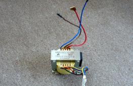
Eaton 5P 1150i UPS internals
This transformation is allowed only by uninterruptible power supplies with a battery start function. That is, the UPS must initially be able to turn on from, without connecting to an outlet.
If the UPS has a standard outlet, 220 volts can be removed from its contacts. If there is no such outlet, it will be replaced by an extension cord connected to the “output” socket of the uninterruptible power supply. The extension plug is removed, after which the wires are soldered to the contacts of the “output” socket.
The main disadvantages of such converters:
- The recommended operating time for such an inverter is up to 20 minutes, since UPSs are not designed for long-term battery operation. However, this drawback can be eliminated by embedding a computer fan operating from 12 V into the UPS case.
- Lack of battery charge controller. The user will have to periodically check the voltage at the drive terminals. To eliminate this drawback, you can embed a regular automotive relay into the design of the converter by soldering the red wire behind the fuse to pin 87. If connected correctly, such a relay will turn off the power supply when the battery voltage drops below 12 volts.
How to make a power supply from an uninterruptible power supply
In this case, of the entire design of the uninterruptible power supply, only . Therefore, the user who decides to remake the UPS in this way will have to either gut the entire UPS, leaving only the housing and transformer, or remove this part and prepare a separate housing for it. Then proceed according to the following plan:
Using an ohmmeter, the winding with the highest resistance is determined. Typical colors are black and white. These wires will be the input to the power supply. If the transformer remains in the UPS, then this step can be skipped - the entrance to the homemade power supply in this case will be the “input” socket at the end of the UPS, connecting the device to the socket.
Next, an alternating current of 220 volts is supplied to the transformer. After this, the voltage is removed from the remaining contacts, looking for a pair with a potential difference of up to 15 volts. Typical colors are white and yellow. These wires will be the output from the power supply.
The input to the power supply is formed from wires on one side of the core. The output from the block is formed from wires located on the opposite side.
A diode bridge is installed at the output of the power supply.
Consumers are connected to the contacts of the diode bridge.
![]()
Transformer
The typical voltage at the output of the transformer is up to 15 V, but it will drop after connecting it to a homemade load power supply. The designer of such a device will have to select the output voltage through experimentation. Therefore, the practice of using a UPS transformer as the basis of a power supply for a computer is far from the best idea.
Converting an uninterruptible power supply for charging
In this case, a minimal transformation similar to that described in the paragraph above is not needed. After all, the uninterruptible power supply has its own battery, which is charged as needed. As a result, to turn the UPS into a charger you need to do the following:
Locate the primary and secondary circuit of the transformer. This process is described in the paragraph above.
Supply 220 volts to the primary circuit by inserting a voltage regulator into the circuit - as such, you can use a rheostat for light bulbs, replacing a traditional switch.
The regulator will help calibrate the voltage on the output winding in the range from 0 to 14-15 volts. The place where the regulator is inserted is in front of the primary winding.
Connect a 40-50 ampere diode bridge to the secondary winding of the transformer.
Connect the terminals of the diode bridge to the corresponding poles of the battery.
The battery charge level is monitored by its indicator or voltmeter.
Write a letter
For any question you can use this form.
The most famous are computer uninterruptible power supplies (UPS, or UPS). A regular computer uninterruptible power supply enough for a few minutes necessary for the user to save data and complete work normally. In this case, it is useless to talk about long-term power supply for many consumer devices. If you need to ensure the operation of smart home systems, heating devices or other household appliances, you will need a more powerful device designed for long-term operation. You can purchase a ready-made device, but for people who are trained and knowledgeable in electrical engineering, the option of making their own uninterruptible power supply is attractive. This will help to save money to some extent, give you the opportunity to apply your skills and end up with a device that best suits the needs of a particular consumer.
Ensure uninterrupted power supply to devices for quite a long time Only devices based on powerful and capacious batteries can be used, for which it is necessary to use a charger of appropriate power and an inverter that converts direct voltage into standard 220 V. The greatest difficulty will be the manufacture of the inverter, since depending on what kind of sine it produces - pure or meander - different types - it depends which devices can be powered from the received kit. Some devices do not perceive pulsed voltage with a large number of high-frequency harmonics - this must be taken into account when planning the creation of a UPS.
Most users prefer to use a ready-made, factory-assembled inverter, since it is quite difficult to provide the required frequency for the home and all consumers.What will you need?
 To make a UPS with your own hands, first of all you will need batteries from a powerful car- KamAZ or other similar truck. It is necessary to use a pair of 12 V batteries connected in series and with a capacity of 190 Ah or more. Small-capacity devices charge faster, but are more demanding on the charging mode and react painfully to overcharging. In addition, you will need a charger with sufficient power and an inverter.
We make a powerful uninterruptible power supply based on a standard UPS by connecting two KAMAZ batteries to it. We also do automatic ventilation when switching to autonomous mode.
This is the reality that Russian power grids force consumers themselves to care about the stability of the electricity they receive. In our case, it is necessary to solve two important problems: a large voltage drop (typical of the hot/cold season, when air conditioners/electric heaters are turned on) and a complete power outage (“knocking out” of machines, accidents at a substation, etc.).
If the first problem is easily solved by installing an autotransformer, which makes it possible to obtain a stable voltage of 220 volts at the output, then the second requires the organization of an uninterruptible power supply system designed for a long period of autonomous operation.
You can organize uninterrupted supply of a country house or garage by upgrading computer systems. After two years of operation, the internal batteries in any UPS degrade. Uninterruptible power supplies with non-working batteries have been repeatedly observed on the radio market at a symbolic price of 1000 rubles.
For long battery life, an uninterruptible power supply must be connected to high-capacity batteries. The best option would be starter batteries from KAMAZ vehicles - 140 Ah. Since most powerful uninterruptible power supplies use batteries with a total voltage of 24 volts, we need a pair of batteries connected in series. The duration of the autonomous power supply will depend on the condition of your batteries.
First of all, we take out and throw away the faulty battery. For the convenience of connecting an external high-capacity battery, we need to make contact clamps (preferably red and black, indicating plus and minus, respectively). To do this, we make two holes on the front panel of the uninterruptible power supply, fix the contact clips and solder the wires to them that went to the internal battery.
Long-term operation in the state of converting battery energy into a voltage of 220 volts is accompanied by large heating. To prevent premature failure, it was decided to install two conventional fans measuring 80x80x25 mm on the ventilation grille.
The fans are connected in series. To start the fans in conversion mode, we use an LED, which indicates the operation of the uninterruptible battery power supply. We solder the leads of the LED to the windings of a small relay with wires. We solder a wire from the incoming positive of our battery to one of the relay contacts. The second is a free red fan wire. We solder the free black wire of the fan to the incoming negative of the battery.
All! Now, when the uninterruptible power supply switches to battery mode, the cooling will automatically turn on.
The requirements for the device were: small-sized, low-cost, silent in operation with high efficiency that can ensure autonomous operation of the modem for three or more hours.
There are two types of uninterruptible power supplies: soft start and hard start. In our case, a system with a hard start is desirable.
In this case, the modem does not turn off due to the lack of mains voltage due to the instantaneous operation of the uninterruptible power supply.
First What we need are batteries. The ideal option is 18650 batteries (4 pcs., capacity: the more, the better).
Second- this is the body. A case with a board from PowerBank will do. It has six compartments for 18650 batteries. We will use two compartments to accommodate all electronics.
Third– DC-DC converter that provides 2 amperes (hereinafter referred to as A) output current
Quadruple– Step-down stabilizer with the ability to stabilize current and voltage. It is needed to charge the UPS battery from the modem’s power adapter (its current is about 3 A).
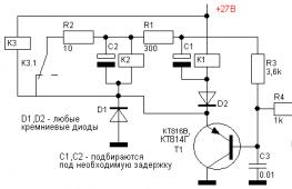
Fifth– Electromagnetic relay (necessarily with a voltage of 12 volts). The relay current is basically not important.
Sixth– Two resistors of any power. One with a resistance of 150 Ohms, the second - 1 kOhm.
Seventh-Direct conduction transistor BD 140. It is important that it is direct conduction.
Eighth– Any small-sized switch with latching. Current not less than 1 A.
At the output of this stabilizer, you need to set the voltage to about 4.1-4.2 V, which is equivalent to the voltage of fully charged lithium-ion batteries. You also need to set the maximum charge current to about 1.5-2 A. This is done using trimming resistors on the step-down stabilizer board.
The Dc-Dc boost converter board also needs to be configured. To do this, we connect it to one bank of lithium battery and, using the built-in tuning resistor, set the output voltage to about 12 V. It is this converter that will provide power to the modem.
Now let's look at how this whole system works.
If there is mains voltage, power from the modem adapter (about 12 V) is supplied to a step-down stabilizer, which is charged by lithium batteries. In this case, the transistor is open, and power through its junction is supplied to the relay and the latter is activated, opening the power supply network of the Dc-dc converter. If there is no power from the adapter, for example when the mains voltage is turned off, the transistor closes and the power supply to the relay winding stops. Contacts 1 and 2 close. Power from the batteries is supplied to a converter, which increases the voltage from the lithium batteries to 12 V, ensuring uninterrupted operation of the modem. The switch is designed for emergency shutdown of the uninterruptible power supply.
Please pay attention to the diode that is in the circuit.
It is connected in such a way as to prevent current from flowing from the output of the boost converter to the input of the buck regulator.
DIY washing machine repair