A simple stabilizer for LED lamps, strips, etc. How to get a non-standard voltage The simplest DIY voltage stabilizer
Today I will write about something that I should have written about a long time ago, because of the backlighting and LED crafts becomes more and more, but sometimes one or two LEDs burn out in them, and the beauty fades into the background, so to prevent this from happening, you need to install stabilizers for LED products. By installing such stabilizers once, we achieve durability and uninterrupted operation of our LEDs.
A simple do-it-yourself LED stabilizer
It's no secret that led light bulbs, used in cars, as well as most LED strips, are designed for a constant voltage of 12 volts. And also everyone knows that the voltage in the on-board network can exceed 15 volts, which can be destructive for sensitive LEDs. As a result of sudden voltage surges, LEDs can fail (flash, lose brightness, or, more often, simply burn out).
You can fight this problem and it’s even necessary, especially since it doesn’t require any special knowledge or expenses. As you probably already guessed, to combat high voltage (for LEDs) you need to purchase and manufacture a voltage stabilizer. A 12-volt stabilizer can be easily found in any radio parts store. The markings may vary, I took KREN 8B (15 rubles) and a 1N4007 diode (1 ruble). A diode is necessary to prevent polarity reversal and must be soldered to the input of the stabilizer.
Connection diagram
Blanks
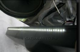
I started connecting the stabilizers to the leg lighting (I had already done this). As you can see in the picture, the voltage in the on-board network with the ignition off (battery voltage) is 12.24 volts, which is not scary for an LED strip, but the voltage in the on-board network with the engine running is a threatening (for LEDs) 14.44 volts. Next, we see that the stabilizer copes with its task perfectly and produces an output voltage that never exceeds 12 volts, which is good news.
An isolated example, in any other email. in circuits the situation is similar
Connection diagram
Right front door


In most electronic devices, all voltages are relatively standard: 3V, 5V, 9V, 12V and so on.
As for the output voltage, electrochemical current sources are usually standard: batteries (1.5V, 9V), accumulators, and so on.
But there are times when you need to get an unusual voltage: for example, 6V or 8V. Tell me, does this happen extremely rarely? Not at all...
Let me digress a little from the topic and give a real example from real practice:
In some models of Sharp TVs, the video processor was powered through a three-legged stabilizer AN7808 (that is, 8V). At a lower voltage, the brightness is turned off; when 9V is supplied, the TV works, but there is no color and the frame size is increased. In the good old days, it was quite problematic to find a “native” 8-Volt stabilizer and you had to “get out” with native Soviet KR142EN type KRENs for a fixed voltage of 5 and 12 Volts.
There are two options to solve this problem:
1. Make an adjustable power supply.
2. Change the stabilization voltage of the stabilizer chip.
Let's consider both options:
regulated power supply
There are many diagrams of regulated power supplies on the Internet. You can find various circuits both on transistors and on microcircuits, with and without protection, but we will consider the simplest version of an regulated power supply - on an LM317 series microcircuit. It can be used to make simple regulated power supply with output voltage within 1.5....30V and current up to 1.5A. By the way, it also has a domestic analogue - it’s called KR142EN12A. Its connection diagram is as follows:
As we see, there is nothing complicated or tricky: the most ordinary diode bridge, a pair of capacitors at the input and output, and a control circuit.
Option two:
How to change the stabilization voltage of Krenka
Here, in general, there is nothing tricky either: it’s enough to simply connect the middle (the one that is the “common” output) of Krenka via a zener diode. See diagram:

The output (and stabilized!) voltage will rise to the value of the stabilization voltage of the zener diode.
That is, if we take a 5-volt Krenka and install an additional zener diode, say, at 3.3V, then at the output we will get 5+3.3=8.3V.
But what if you suddenly need to raise the voltage not much, say just 0.5....1.5V? It’s also not difficult: such zener diodes do not exist, but instead of a zener diode you can use an ordinary diode (only it is turned on not like a zener diode, but vice versa - with the cathode to the “common”). See picture:

The thing is that a voltage drop is created at the p-n junction of the diode:
for silicon diodes it is about 0.6-0.7V, for germanium diodes 0.3-0.4V.
It is this property that can be used: if you install, say, two silicon diodes connected in series, then the voltage at the Krenka output will rise by approximately 1.4V.
A small addition: in the “latest” domestic TVs (which were still produced in the mid-to-late 1990s) one could find power supplies where the 12-Volt stabilizer was made on the KR142EN8G microcircuit with the middle output connected through a tuning resistor. But the adjustment range of such a scheme was, frankly speaking, not very good.... So everything that was written above is more effective.
And finally: the main part of the material and pictures were borrowed from the Practical Electronics website (with prior consent!!)
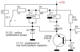
Often, radio amateurs are faced with the problem of obtaining a stabilized power supply with high current. But the simplest cranks cannot withstand such currents. I propose a circuit that can pass a current of up to 7.5 Amps at a voltage of 12V ± 0.1V. The device consists of a power transformer, a diode bridge (at least 10 Amperes), two capacitors for ripple suppression, a KT818G transistor, a KREN8A stabilization chip, and a 43 Ohm resistor.
Device operation:
When the device operates without load, current flows through the diode bridge, capacitors, and stabilization chip. At the output we get 12V. When the circuit is loaded, for example, by a low-frequency amplifier, the KT818G transistor opens, and the entire load flows through it, bypassing the stabilization chip. Thus, the stabilization chip performs only the stabilization function.
The stabilization chip and the transistor must be mounted on radiators, either on two different ones, or on one, but then they will have to be isolated.

The circuit uses radio components:
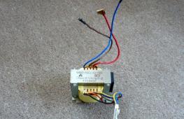
First of all, you need a power transformer
Diode bridge (from 8A - 10A) (no less - more is possible)
Electrolytic capacitors: 100 µF* 35V, 1000 µF * 16V.
Resistor 43 Ohm (0.5 W) no less - more is possible
Transistor KT818G
Stabilization chip KREN8A
Cost about 100 rubles. (without transformer)

In the diagram, parts can be replaced with analogues.
The radiators may also get a little warm - this is acceptable.
List of radioelements
| Designation | Type | Denomination | Quantity | Note | Shop | My notepad |
|---|---|---|---|---|---|---|
| Linear regulator | UA7808 | 1 | KREN8A | To notepad | ||
| VD1 | Diode bridge | 8-10A | 1 | Not less than 8A | To notepad | |
| VT1 | Bipolar transistor | KT818G | 1 | To notepad | ||
| R1 | Resistor | 43 Ohm | 1 | 0.5 Watt | To notepad | |
| C1 | 100uF 35V | 1 | To notepad | |||
| C2 | Electrolytic capacitor | 1000uF 16V | 1 | To notepad | ||
| S1 | Switch | 1 | To notepad | |||
| R | Connector | 1 |