Pipes and manifolds for heated floors. Installing a manifold for a heated floor with your own hands
It is an integral part of the auxiliary or main underfloor heating system. Its design, assembled according to a complete professional scheme, is quite complex, as it consists of many interdependent elements. However, in many apartments, small private cottages or country houses, the heating system is equipped according to a lightweight scheme. It can contain only a few radiators and two or three TP circuits, which makes it possible to install them in a common cabinet with a simplified manifold (comb). Thus, in most cases, assembling a manifold for a heated floor with your own hands is quite feasible. And setting up such a system will not cause any particular difficulties.
What is required to assemble the main distributor for the TP?
The varieties, configuration and purpose of individual node elements of collectors have already been described in the article “”. Therefore, here we briefly recall that for assemblies of its various types you will need:
- a pair of basic combs (monoblock or composite) for supply and return of coolant;
- two-way ball valves. Two of them will be required to cut off the flow and return from the primary (radiator) heating circuit. The rest can be used as shut-off valves at the inlet/outlet of underfloor heating circuits into the corresponding comb;
- manual valves - rotameters for balancing the coolant flow in each branch. They are usually mounted on the supply manifold for each TP circuit;
- thermostatic valves, manual or controlled by a controller with servo drives;
- a circulation pump, which is advisable to purchase as part of a ready-made mixing group, together with connection taps, a bypass, a mud filter, etc. It should be noted that when installing a manifold for a heated floor with your own hands using a simplified scheme, you can do without a pump, using only an automatic three-way valve or two-way valves like Unibox;
- control devices – pressure gauges, thermometers;
- security groups;
- fittings and various connecting elements for attaching underfloor heating pipes to collectors, etc.
Design of a collector unit
A pre-designed diagram will help simplify the assembly of the comb. Having even an amateur sketch at hand, you will already be insured against many editing mistakes. But a well-thought-out diagram of a heated floor collector, drawn up by a professional, should already take into account a number of parameters and practical aspects. The most important among them:
- number of heating branches (loops);
- determination of characteristics of consuming devices - diameter and footage of circuit pipelines, as well as hydraulic losses in them;
- type of heating boiler, its main operational capabilities - thermal output, circulation pump power, coolant heating temperature;
- the presence of additional equipment in the heating system - storage and damper tanks, pressure gauges, thermometers, safety groups, hydraulic arrows, etc.;
- the need to provide for the possibility of scaling - connecting additional circuits, improving the control system - installing automation devices on existing control elements, as well as units that provide remote access.
IMPORTANT! A professional connection diagram for a heated floor collector does not just give an idea of which tap is responsible for a certain area. It allows you to place the pipelines in a more orderly manner, and in the future facilitate the setup and management of the heating system.

Choosing a place to install the TP manifold
It is very important to determine the optimal location where the underfloor heating collector will be installed. It is desirable that it be located in the geometric center of the building at an equal distance from the main consuming circuits and the heating boiler. Of course, in practice it is impossible to maintain the exact distance from the comb to the heating loops. And the loops themselves rarely have the same length, which leads to an imbalance in their hydraulic resistance. As a result, the coolant will tend to circulate in a short branch, and long ones may result in a lack of flow. And although this problem can be eliminated by installing rotameters or adjustable valves, one should still strive to achieve symmetry in the laying of pipelines.
When choosing a place to place a collector for heated floors in standard apartments or small cottages, you have to take into account the features of their layout. Since the manifold cabinet is not the smallest in size, in conditions of limited living space it is usually located in a closet or in a wall technological niche. However, if the house is larger and already has a separate boiler room, then the distribution combs with all the piping are placed directly next to the heating boiler. In large houses with two or three floors, it is even easier to maintain a geometric mounting center. In them, the collector can be installed in the space under the stairs.
Manifold cabinet
Its presence in the equipment set does not at all affect the functioning of the water heated floor system. However, the collector (installation) cabinet is responsible for the aesthetic component of the perception of the thermal installation, as well as for the safety of its components and their settings. It protects the system's controls, some of which are quite sensitive to external mechanical influences. Sometimes the material itself, for example, a polypropylene manifold, despite all its reliability, can be damaged. Considering these factors, it is recommended to choose boxes with lockable doors.
The mounting height of the mounting cabinet is selected based on local conditions and the wishes of the owner of the facility. It is not strictly regulated by regulatory documents. It should be taken into account that placing combs lower than 50 cm from the floor level is undesirable. The recommendation is due to the practical convenience of supplying pipes for connection and fastening to the manifold. The optimal mounting height for the cabinet is about 1 m.
![]()
TP manifold assembly
Assembling and installing a manifold for a heated floor, purchased as a complete set, according to the instructions supplied by the manufacturer, will not be difficult even for inexperienced home craftsmen. In this case, the most crucial point is to control the tightness of the interfaces of elements and assemblies. And since in factory kits most of the unfinished connections are provided on rubber or silicone gaskets (in rare cases on fulente), this task can be solved quite easily by any installer.
For those who have some experience in plumbing work, it will be more profitable to purchase and assemble a manifold from various elements on their own. By doing this, you will be able to save up to half the cost compared to a ready-made constructor. In addition, it is possible to assemble exactly the configuration that will best satisfy the user’s needs.
DIY polypropylene manifold
Polypropylene manifolds are among the most affordable. However, it should be taken into account that they take up slightly more space than prefabricated metal ones, and even more so. It can also be problematic to install flow meters and other devices for automatic adjustment and control of coolant supply into a polypropylene structure.
The elements for assembling the comb can be fittings used in heating or water supply systems, or finished, factory-cast products. In the latter case, the manufacturer sets a fixed number of taps, which cannot be increased on the selected model.
IMPORTANT! It is more convenient to use a manifold assembled from polypropylene fittings if its design is installed in a boiler room, boiler room or other technical room. After all, with a number of heating circuits of 5 or more, the plastic assembly turns out to be too bulky.

Accessories and tools
To completely assemble a polypropylene heating manifold with your own hands, you will need a special mounting soldering iron - for diffusion welding, and from materials and ready-made elements:
- no more than 1 m of polypropylene pipe PN 20-25 without an external reinforcing layer Ø 32 mm;
- 1-2 m of pipe PN 20-25 Ø 32 mm with internal or external reinforcement. This position can be dispensed with if the manifold does not include the mixing unit piping;
- tees Ø 32 mm (in a quantity equal to the number of TP branches) with bends corresponding to the diameters of the transition threaded couplings for connecting circuits;
- transition couplings plastic/metal. It is better to take models with union nuts - American ones;
- Ball Valves;
- balancing valves - suitable for heating radiators.
Build process
A homemade manifold for heated floors made of polypropylene is made as follows:
- A piece of polypropylene pipe without external reinforcement is soldered to one of the inputs of the Ø 32 mm tee. Its length depends on the skill of the installer. If you are good with a soldering iron, then 5-7 cm is enough - 2 cm per landing depth of the pipe entering the tee and 1-3 cm between adjacent fittings. But they can also solder closely.
- A plastic/metal adapter with pipe thread or American thread is soldered to the lower branch of the tee. These steps are repeated until the number of taps is equal to the number of heating circuits (possibly +1 in reserve). It is necessary to make two such combs, because one polypropylene manifold is intended for supply, and the other for return. However, there is no structural difference between them.
- From the end of the comb, a transition coupling is soldered onto metal of the appropriate diameter. Subsequently, a ball valve will be connected to it to block the general supply of coolant to the TP system (if necessary).
- A tee (or just an elbow) is installed at the opposite end to connect the air vent.
- After assembling the polypropylene comb structure, shut-off valves or control valves are screwed to the adapter couplings, and an automatic or manual air vent is installed.
IMPORTANT! It is better to try to weld the plastic fittings of the tees close to each other. Otherwise, the already rather large design of the polypropylene manifold will take up an even larger volume.

The simplest model of a homemade plastic distributor is made in a similar way. If you plan to install various service and automatic devices, then you should provide for soldering the appropriate fittings for them. For example, to install flow meters, it is necessary to replace the tees on the supply comb with cross parts made of polypropylene. In this case, both branches of each cross are equipped with couplings with metal transitions. A metal (brass or bronze) extension of the appropriate diameter and length is screwed into the upper coupling to install the flow meter, and a pipe is connected to the lower coupling. In this way, a polypropylene floor heating distributor can be equipped with any measuring device, a safety group device or a special type of shut-off and control valves.
DIY metal comb for heated floors
To make metal combs yourself, brass or bronze fittings, tees, fittings, and plugs are used. The general layout and assembly sequence resembles a similar process for a polypropylene comb, which only takes a little longer. This is due to the fact that each threaded connection must be carefully sealed using fumlenta, flax tow or special sealants.
When purchasing fittings and other plumbing parts, you should pay attention not only to their attractive price and shiny newness, but also to the true quality of the material. Firstly, it’s good to understand which manufacturer’s products you will be dealing with. If the seller provides a certificate for his products, that will be absolutely wonderful. Secondly, just by some external signs one can guess whether it is worth getting involved with such a product. So, good factory parts are, at a minimum, heavier than fakes and have thicker walls. The use of thin-walled “Chinese” tees, although it will noticeably reduce the cost of the comb, will critically reduce its reliability. In addition, working with counterfeit goods is quite difficult - low-quality material can crack at any time.
IMPORTANT! The use of high-quality bronze fittings brings a homemade manifold for heated floors closer in cost to a factory product - there will be savings, of course, but very insignificant. If installation of adjustable flow meters using crosspieces is required, then self-assembly of the combs becomes completely unprofitable.

Practical aspects of installing a water TP distributor
- It is better to assemble and install the manifold for heated floors before rolling out the pipelines of the circuits. In this case, one end of the pipe is immediately fixed at the place of permanent connection, then, after laying out the loop, the second is fixed.
- By installing a comb with an automatic air vent at the top point of the system, you will forever get rid of the problem of air venting. If the distributor is located, for example, in the basement, then you will have to install additional valves to remove air somewhere on the hinges themselves.
- Each of the combs must have a slight installation slope (rise to the air vent) to relieve air plugs.
- When choosing a collector assembly scheme without a mixing unit, in which the temperature in the loops is controlled by thermostatic valves (RTL regulation), the length of the pipelines in the heating branches should be taken into account. It has been noted that this scheme works well if the length of the pipe loop does not exceed 50 m for a pipe Ø 16 mm. If the length of the branches is higher, then a heated floor collector circuit with
conclusions
The decision whether to make a manifold for a heated floor with your own hands or purchase a ready-made one should be made based on the level of your installation skills, requests for the comb configuration, as well as financial capabilities. It will be important to consider that:
- if it is necessary to connect 3-5 circuits, and the distribution unit is planned to be located in a manifold cabinet, then it is optimal to use compact metal fittings or ready-made monoblocks;
- for a heated floor system with 5-7 circuits or more, the use of polypropylene combs is economically justified. However, in this case it is better to install them in a specialized room;
- For heating systems that are planned to be controlled automatically, it is advisable to buy a manifold for a heated floor in a complete factory configuration.
The collector is a device responsible for the distribution of hot water and there is no way to do without it when installing a warm floor that gives the house comfort. Making it yourself and with your own hands is not easy, but it is quite possible. How to make such a device from polypropylene? Everything will become extremely clear after viewing photographs and videos about the installation of the system, as well as studying the detailed instructions.
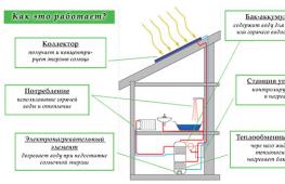
How does a heated floor system work?
Conventional radiators, which have recently been the only possible installations for heat transfer in the house, are gradually being replaced by warm floors and ceilings. They can operate using electricity or hot water. The second option is considered more practical and, if desired, you can construct a water heated floor with your own hands. There is nothing complicated about the heating system. Its scheme includes several elements:
- Water heating boiler. It should heat the water well enough, distributed throughout all the pipes, and still have some power reserve. If this is expressed in numbers, then the additional productivity should be equal to 15-20% of the total capacity of heated floors.
Advice. When you plan to heat a room larger than 120 m², it is advisable to purchase a boiler with a built-in circulation pump or install it separately.
- To avoid having to drain water from the entire system during repairs or in the event of an accident, shut-off valves are installed at the inlet and outlet of the boiler.
 Water heated floor
 - Pipes, which can be polypropylene, or can be made of special cross-linked polyethylene, for distributing water and pipes for laying out the floor surface. The diameter of these pipes must be at least 16-20 mm, and they must also withstand temperatures up to 95°C and a pressure of 10 Bar.
- The collector is a splitter with taps. This is a necessary element to which several circuits are connected from the central supply line of warm water and the return intake of already cooled water.
How does the collector work?
A manifold is a kind of center of pipes, valves, pressure gauges, fittings and other auxiliary components made of metal or plastic. The device performs the function of a mixer of technical water, which comes from the heating circuits. It also distributes the coolant back through the pipes.
As a result of the operation of the collector, the water temperature in different areas is equalized and, accordingly, the air in heated rooms is stably heated.
Any heating system works according to the following principle: process water heated in the boiler is sent through connected circuits and pipes. During their passage, it cools down and, with the help of a circulation pump, returns to the collector through the return line, where it mixes with the hot coolant. The ratio of hot and cooled water is regulated by special valves, and temperature and pressure are monitored by sensors.
 Collector
 The temperature in conventional radiators is 70-95°C, and in a heated floor system it should be 30-50°C. If it increases, deformation of the floor covering and drying of the air in the room may occur. Walking on a hot floor will also be impossible.
It is precisely in such cases that the work of the collector is required, because the boiler is capable of producing coolant of only one temperature.
When the sensor detects an increase in temperature, the valve closes and hot water flows in smaller quantities. After the coolant has cooled, the valve opens again. Cooled process water from the return pipe is supplied under pressure, and hot water from the boiler is supplied as needed.
Components of a heated floor collector
- Mixing valve.
- Balancing valves and shut-off valves.
- Pressure gauge and temperature sensor.
- Circular pump.
- Automatic air vent.
For self-assembly you will definitely need various fittings, adapters, nipples, etc.
 Reservoir components
 Self-assembly of a polypropylene manifold
To assemble the collector you will need:
- ball valves, preferably American;
- pipes with a diameter of 25 and 32 mm;
- couplings with internal thread 32x"1" and 25x3/4;
- couplings with external thread 25x3/4;
- plugs Ø32 mm;
- tees of suitable diameter;
- sealant, preferably thread sealant;
- security group;
- automatic air vent device.
Installation diagram
The distribution manifold consists of two parts. The first part receives heated process water coming from the boiler, and the second part receives the already cooled coolant, that is, the return flow.
- All parts that make up the comb are connected using high-temperature treatment with a special soldering iron for plastic pipes.
- An automatic air vent and a safety group are connected to one part of the collector.
- A tap is connected for emergency drainage of water.
- A tap and an air vent are placed on the second part of the manifold. Pipes will be connected here to return the cooled coolant.
- A circulation pump is connected to the return line, which creates pressure and the coolant begins to forcefully move through the pipes and heating circuits. It is mounted approximately to the boiler, that is, the arrow on the pump should be directed towards the boiler. This installation will allow the device to last much longer.
Advice. To save fuel, it is better to install a three-way valve after the circular pump.
The places that were intended for soldering the tee should be left on both combs and only after accurately determining where it will be located will it be possible to weld the plugs. The presence of a tee is necessary if in the future there is a need to expand the comb.
In order for process water to circulate in the system in the correct direction, it is necessary to install a so-called “reverse” valve.
 Collector installation diagram
 After completing the installation of the heating circuit, you need to connect both collectors to it and install the boiler in the location planned for it. Next, you need to screw one tap into both parts of the collector. The expansion tank is soldered on the supply side. The installation is completed by connecting the heating boiler to the collectors.
Advice. If the house in which the collector is installed has two floors, then it would be reasonable to connect four heating circuits to its terminals, respectively, two for each floor.
Warm floors create a special atmosphere in the house, and the installation of such a heating system should be taken very seriously. Before assembling it yourself, you need to carefully consider every little detail and review the various variations. If there is any error in the calculation, then further operation and maintenance of the system as a whole will become impossible and everything will have to start again.
Warm water floor: video
The defining task when designing an autonomous heating system is the uniform distribution of the coolant. This task in the heat supply system is performed by a control and regulation unit - the distribution manifold.
The uninterrupted operation and reliability of the heating circuit largely depends on the correct choice of device, high-quality installation and connection. If you want to install a heating distribution manifold with your own hands, then you need to carry out calculations and design the wiring in advance.
We will help you resolve these issues. In the article, we examined the design of the collector group, identified the pros and cons of a heating system with a comb, and described the rules for the design and installation of a distribution unit.
The material is supplemented with practical advice on selecting components, assembling and connecting the collector to the heating system.
When arranging a water pumping unit, you must adhere to the rule: the total sum of the diameters of all branches should not be greater than the diameter of the supply main.
Let's apply this law to the heating system, but it will look like this: a boiler outlet fitting with a diameter of 1 inch is allowed for use in a double-circuit system with pipes with a diameter of ½ inch.
For a house with a small cubic capacity that is heated exclusively by radiators, this kind of system is considered productive.
For utility rooms, it will be enough to set the temperature to 10-15 °C; for living rooms, a temperature of up to 23 °C will be comfortable; in underfloor heating circuits – no more than 37 °C, otherwise the main coating may be deformed.
In practice, a private cottage is equipped with a more modernized heating circuit, where additional circuits are installed:
- heating of several floors;
- utility rooms, etc.
When a branch is connected, the level of operating pressure in the circuits becomes insufficient for high-quality heating of all radiators, respectively, and the comfortable atmosphere will be disrupted.
In this case, a balancing unit is installed for a branched heating main using a distribution manifold. Using this method, it is possible to compensate for the cooling of the heated coolant, which is typical of traditional one- and two-pipe schemes.
By means of equipment and shut-off valves, the required coolant temperature indicators are adjusted for each of the lines.
Main characteristics of the collector system
The main difference between the collector and standard linear method of redistribution of the coolant is the division of flows into several channels independent of each other. Various modifications of collector installations can be used, differing in configuration and size range.

The collector heating circuit is often called radiant. This is due to the design features of the comb. When examining the device from the top point, you will notice that the pipelines extending from it resemble an image of sun rays
The design of the welded manifold is quite simple. The required number of pipes is connected to the comb, which is a round or square pipe, which, in turn, are connected to individual lines of the heating circuit. The collector installation itself is interfaced with the main pipeline.
Shut-off valves are also installed, through which the volume and temperature of the heated liquid in each of the circuits is regulated.

A manifold group, complete with all the necessary parts, can be purchased ready-made or assembled independently, which will significantly reduce the cost estimate when designing heating
The positive aspects of operating a heating system based on a distribution manifold are the following:
- Centralized distribution of hydraulic circuit and temperature indicators occur evenly. The simplest model of a two- or four-circuit ring comb can balance the indicators quite effectively.
- Regulation of heating main operating modes. The process is reproduced due to the presence of special mechanisms - flow meters, mixing unit, shut-off and control valves and thermostats. However, their installation requires correct calculations.
- Ease of maintenance. The need for preventive or repair measures does not require shutting down the entire heating network. Due to the sliding pipeline fittings mounted on each individual circuit, you can easily shut off the coolant flow in the required area.
However, there are also disadvantages to such a system. First of all, pipe consumption increases. Compensation for hydraulic losses is carried out by installing a circulation pump. It must be installed on all collector groups. In addition, this solution is only relevant in heating systems.
Modifications of collector units
Before you begin assembling the collector assembly, it is necessary to determine its functional load. The equipment can be installed in several sections of the heating main. Based on this, the necessary equipment, dimensions and level of automation of the work cycle are selected.
In fact, for the full operation of such a node, two devices are needed. Using a comb, the coolant is distributed along the contours of the central supply pipeline. The return collector channel is represented by a collection mechanism and the point of departure of the cooled liquid into the boiler.

The collector heating circuit is selected based on the calculation of the required functionality and installation location. The choice of material for making the device does not affect the number of significant mechanisms
Installation of a homemade distribution group may be required when installing water-heated floors or for preparing standard heating with radiators.
Distinctive features of both options are their sizes and components:
- Boiler room. The welded manifold group is made of pipes with a diameter of up to 100 mm. A circulation pump and shut-off valves are installed on the supply side. The return ring is equipped with shut-off ball valves.
- Warm floor system. Similar equipment is present in this mixing unit. With its help, it is possible to significantly save on coolant consumption, especially if additional flow meters are installed. More information about the mixing unit in a heated floor system is written in.
Each of these solutions provides an individual installation scheme. Correct installation of all elements can be carried out only after detailed calculations of all operating point parameters.

The comb can be made of the same material as the pipeline. If it is different, adapters will be used to connect the collector
There are also differences in the quantity required. In the boiler room, each line is equipped with this device. For heated floors, only one installation is provided.
Distribution node design
There is simply no universal scheme for a radiant heating project. Each case is individual, which is why the unit is equipped with the necessary devices privately. However, it is worth familiarizing yourself with the general recommendations and rules.
Rules for installing the comb
Installation of the collector is not possible in an apartment. However, there is an exception to the rule - in some houses, when all communications are installed, additional valves are installed, through which the heating circuits are connected. This device allows for individual wiring of the collector.
The schematic arrangement of heating should be drawn up in such a way that the location is on the comb. This option is considered optimal, because over time, accumulated air will need to be released from the circuits.
Features of the beam group
The radial wiring group has many nuances, but some of them are also typical for heating of other modifications.
Features of the comb system:
- The circuit package must include a volume of more than 10% of the total volume of the coolant.
- The optimal location of the expansion tank is on the return pipeline in front of the circulation pump, since the temperature regime is lower here.
- If a thermo-hydraulic distribution is used, the circuit is designed so that the tank is located in front of the main pump, which is responsible for the forced movement of water in the boiler piping.
- The circulation pump is installed in a strictly horizontal position. If you do not adhere to this rule, at the first air lock, the device will lose cooling and lubricant.
The distribution group can be assembled from various materials: polypropylene or metal. The selection is made based on work skills and the availability of tools for connecting parts.

The optimal heating temperature for radiators in a private cottage is 55-75 °C, pressure up to 1.5 atm. The operating mode of the warm floor circuit warms up to 40 °C. Based on these characteristics, the degree of stability of the pipes is selected
The process of selecting pipes for installing a distribution group is also considered important.
The main factors taken into account when choosing contour elements:
- Purchase of pipes only in coils. Due to this, connections are not made in the wiring installed under the concrete screed.
- Heat resistance and tensile strength must be determined individually, based on the technical data of the heating system.
Due to the predictability of the operating characteristics, autonomous heating can be used. They do not have unwanted connections and are sold in continuous 200 m lines.
The material is heat-resistant and can withstand temperatures up to 95°C with a permissible burst pressure of 10 kg/1 cm 2.

Stainless steel pipe is highly flexible. The bend radius can be equal to the diameter of the product. Installation is carried out according to the following scheme: the pipe must be directed into the fitting and secured with a nut
For a multi-story building, it is preferable to choose a corrugated pipe made of stainless steel.
This material shows excellent technical capabilities to cope with such a load:
- heated coolant up to 100 °C, which is more than enough for the heating circuit;
- pressure up to 15 atm;
- fracture pressure up to 210 kg/1 cm2.
Fittings designed for polypropylene can be plastic or made of brass. The fitting connection is equipped with a locking ring, which is threaded onto the pipeline.
An important characteristic of polypropylene pipes is the memory of mechanical processing, which results in plastic deformation of the substance.
For example, when stretching pipes with an extender and installing a fitting into the connector, after a certain time the pipe will return to its previous state and crimp the part. The contact can be secured with a locking ring.
Heating manifold calculation
Initially, to manufacture a thermohydraulic comb, you will need to calculate its main parameters - length, cross-sectional diameter of the pipes and the number of branches of the heating main. You can calculate these characteristics yourself or use special software.
Conclusions and useful video on the topic
Detailed technical process for assembling the collector group:
Ready-made combs for arranging heated floors, which are not always equipped with the necessary functionality, are, due to their high cost, not available to the general public. Let's see how to assemble a budget version of the design with your own hands:
The distribution group can also be implemented using polypropylene pipes. You can learn how to do this from the video:
Correct selection of components and installation of the collector unit is the key to efficient and reliable operation of the heating main. Due to the minimum number of connections, the risk of leaks is minimized. An important advantage is the ability to control and configure each heating circuit.
Share with readers your experience in assembling and connecting the distribution manifold. Please leave comments on the article, ask questions and participate in discussions. The feedback form is located below.
When the installation of water floor heating circuits is successfully completed, before pouring the screed, it is necessary to connect the underfloor heating pipes to the collector. This is done in order to check the tightness of the circuits and identify manufacturing defects or possible pipe defects that may arise during the installation process.
The operation of testing the pipelines must be carried out, otherwise in the event of an accident after starting the heating, the floor covering will have to be destroyed. After the screed has been completed and the solution has hardened, it is connected to the main pipelines and the system is put into operation. How to properly assemble a manifold for a heated floor and combine it with a mixing unit will be discussed in this material.
The role of the collector in underfloor heating systems
The collector is an element that underfloor heating cannot do without; all pipelines from the heating circuits are connected to it. Since the temperature of the coolant supplied to the network from the boiler room is too high for the operation of heated floors, a mixing unit always operates together with the collector, ensuring the water temperature is within 40-45 ºС.
Mixing units and manifolds for heated floors perform the task of preparing the coolant at the required temperature and supplying it to all circuits.
To understand how the entire assembly works, let’s look at the collector device in more detail. It consists of two horizontal tubes connected to the supply and return lines. The manifold body and parts are made of the following materials:
- brass;
- stainless steel;
- plastic.

The figure below shows a detailed diagram of the underfloor heating manifold; it is usually supplied in this kit by manufacturers:

On the supply tube there are branches with thermostatic valves (actuators), and on the return there are branches with flow sensors. There are plastic caps on top of the thermostats for manual adjustment; twisting them leads to pressing on the rod and blocking the flow. Flow meters or flow sensors located on the return pipe of the manifold for a warm water floor serve to visually monitor the amount of water flowing and perform hydraulic balancing of the system.
Note. The cheapest versions of collectors may not have flow sensors.
In order to control pressure and temperature, a thermometer with a pressure gauge is installed on the manifold, and a special valve is installed to bleed air. The kit also includes plugs, bends, taps and brackets for attaching the unit to the wall or to the metal slats of the cabinet. Many suppliers practice a complete set of the entire assembly, where there is a distribution manifold assembled with a pump and a two-way or three-way valve.

Operating principle
The unit works like this: the coolant circulates through all underfloor heating circuits, driven by a pump. The flow rate in each circuit is controlled by a valve manually or automatically, by a capillary or servo drive. When the temperature in the supply or return pipeline (depending on the circuit) drops below the set value, a two- or three-way valve begins to mix hot water from the system, and the coolant from the return flows into the general network. The figure shows a diagram of the operation of a manifold with an attached water temperature sensor and a two-way valve:

There are several operating schemes for the mixing unit, they use different parts, but its task remains the same: to maintain the required temperature in the underfloor heating system and control the coolant flow in the supply branches.
It is not difficult to assemble the underfloor heating manifold, supplied as a complete set. The tubes for the supply and return coolant are already equipped with valves and flow sensors; they only need to be twisted together if the manifold included is divided into sections of 2 or 3 branches. Then, for the convenience of further assembly, it is better to fix the tubes on standard brackets, then the distributor will be a single unit. Then plugs, connection elements, shut-off valves and control devices are installed.
Note. The delivery set of each product includes instructions, with its help you should assemble and install the underfloor heating manifold.
The next step is to attach the collector to the wall, and after that you can install the circulation pump and valve. There is no point in doing this in reverse order; then it will be inconvenient to attach the entire assembly. The pump and valve with a thermal head or servo drive are mounted in accordance with the selected diagram, after which the main heating pipes coming from the boiler are connected to them, and pipes from the heating circuits are connected to the outlets. There are situations when the distributor is installed not in the boiler room, but in a corridor or other room, then for installation it is better to use a decorative cabinet for the manifold.

Since the cost of a factory-made manifold is quite high, such a unit can be made independently. True, you will still have to purchase a pump and valve for the mixing part, as well as shut-off valves. The most popular way to assemble a homemade manifold is to solder it from polypropylene pipes and fittings. This will require sections of PPR pipe with a diameter of 25 or 32 mm, tees and bends of the same size and valves. The number of fittings and valves depends on the number of heating circuits. Tools you will need are a soldering iron for polypropylene pipes with nozzles, scissors and a tape measure.

Before making a polypropylene manifold, you need to measure and cut sections of the pipe so that after connecting the tees are as close to each other as possible, otherwise the assembly will not look aesthetically pleasing. Then taps and transitions are welded to the tees, and the remaining fittings for connection to the pump are welded to the resulting manifold.

It should be noted that a homemade manifold for heated floors, made with your own hands, will have some disadvantages. For example, there are no thermostatic valves on the branches in the supply line, and there are no flow sensors on the return line. In their absence, the system will have to be adjusted manually, and this does not always give good results. Of course, all these elements can be installed and connected separately, but then the labor costs will be such that it is easier to purchase a finished product made of plastic, whose cost is quite affordable.
Conclusion
Despite the apparent complexity of the mixing and distribution unit, assembling it is not that difficult. The product usually comes with detailed instructions and should be followed. It is more difficult to make a distributor with your own hands, but this is always advisable, since you still need to buy components, and there will also be difficulties in setting up the manifold.
The recently popular heating system for buildings using underfloor heating requires attention in design, selection of components and installation. Manufacturing requires a larger number of components and products than for a system with radiators. This is due to many factors, but the main one is the need to properly distribute the coolant among the branches and control its heating.
One of the required components is the distribution manifold (comb) to which the pipes running in the floor are connected. It performs several functions and without them, installing a heated floor is problematic. Despite the fact that the manifold group for heated floors is manufactured by many manufacturers and supplied to the market in many modifications, there is often a desire to save money and create it yourself.
How does this process work, what can you assemble a distribution manifold from yourself, and what materials are used for this? Let's try to answer these questions.
The underfloor heating manifold is used in heating systems for the following purposes:
- flow distribution;
- temperature control.
Its main purpose is to supply coolant of the required temperature and quantity to each branch of the heated floor. To do this, a mixing unit is installed with the manifold, including a pump, control valves and a bypass (in some versions).
The need for temperature control is due to the fact that boilers generally prepare water at a much higher temperature than required for heated floors. And in order to convert it to the required parameters, the water is mixed with the “return” until the desired temperature is reached.

Types of collectors
In addition to material and technical characteristics, collectors differ in the type of regulation. They can be either without regulation at all or with the use of flow meters, manual shut-off valves and automatic devices.

Without regulation
A manifold for underfloor heating without regulation allows you to create a cheap version of the distribution system. It does not use any control devices, and the coolant flows are distributed depending on the hydraulic characteristics of the system. Despite the cost, this option should not be used, since it is not convenient to use and can create difficulties in the future.

With manual regulation
Mostly those who are trying to save on equipment tend to install this type of collector. This isn't always a bad thing. Savings allow you to direct funds to places where they are most needed. What are the pros and cons of this option?

A manifold with manual regulation has the right to life and can perform its function in maintaining the required amount of coolant in each branch. In this case, the temperature of the coolant is regulated in the mixing unit, and its quantity for each loop is set manually once. Then the system works independently. Brass manifolds of this type have proven themselves well.
This option is especially relevant when installing a heated floor as an additional comfortable element in the heating system. When the main heating is carried out by radiators or other devices, and heated floors only create additional comfort. For the main heating system in the form of a heated floor, it is better to provide more serious automation.
One of the options for regulating coolant flows to each branch extending from the collector is to use a balancing flow meter. This element makes it possible to regulate the coolant flow and visually control it.
The device consists of a rod with a flange, which allows you to control the nominal diameter in the pipeline. It includes a window with graduation, from which you can visually determine the specific coolant flow through the observed branch. The adjustment is made using the adjusting ring under the cap. Its connection to the manifold is carried out using a thread.
A manifold with flow meters is very often used in modern systems due to its low cost and good performance characteristics.

With automatic regulation
Recently, heated floors are often installed, in which collectors with automatic regulation are installed. To do this, servos are used for each loop. They, in combination with thermal sensors for a warm water floor, allow you to regulate the flow of coolant in each branch depending on the readings of the thermal sensor.

To do this, the required section passage is established. Such systems are more expensive than options without regulation or with manual ones, but they are quite flexible and allow you to obtain comfortable living conditions. Do not forget that automatic systems require competent regulation, without which they will not show their full functionality.
What can a collector be made from?
Standard manifolds for heated floors supplied to the market are made of different materials: polypropylene, steel, and various alloys. Metal elements are most widespread due to their quality, strength and reliability.
Separate combs are available with different numbers of polypropylene bends, which can be stacked with each other to create manifolds of different sizes. The same applies to brass elements.
If the task is to install a manifold for a heated floor not made from factory elements, you can use pieces of pipes, tees and other elements of the heating supply network. Large-diameter steel pipes into which pipes are cut to connect pipelines are suitable. There are also options for using polypropylene tees, which are connected to each other using pipe scraps. As a result of this action, a comb of the desired size and characteristics is obtained.

Making a collector with your own hands
If you decide to assemble a homemade manifold for underfloor heating, you should have some experience and understanding of the design of heating systems. First of all, it is necessary to familiarize yourself with the principle of operation and the task of the collectors, and then carry out competent calculations and actual manufacturing.
Calculation
The heating floor collector circuit is selected based on the characteristics of a particular system. First of all, it is necessary to carry out calculations and select pipeline sections. Before production you must:
- Using a pre-developed scheme, determine which branches the underfloor heating system will consist of and their characteristics.
- Calculate all the operating parameters of the system: the temperature of the hot water supplied to the collector, the coolant flow through all branches of the heated floor, the location of the sections.
- It is important to find out the presence and number of heating devices other than those that will be connected to the distribution manifold.
- Select the regulation and control system to be used in the distribution manifold.
- It is necessary to decide on the location of the collector, since its design and the location of the outlet pipes depend on this. Completing this step allows you to connect the heated floor collector optimally.
To create a good distribution manifold that will allow you to properly control heated floors in the house, it is important to pay special attention to the selection of all components and parts. They must be designed to work in such systems.
In order for the selected manifold to perform its function efficiently and not create additional hydraulic resistance for flow movement and noise, the selection should be guided by the following rule: the diameter of the distribution manifold must be selected in such a way that its cross-sectional area is equal to or greater than the cross-sectional area of all pipelines that connected to the device. The same applies to the collecting manifold.
That is, for example, if 4 pipelines with an internal diameter of d=20 mm are connected to the collector, then the cross-sectional area of the collector should be: S = 4(πd²/4) = 1256 mm². That is, the diameter of the pipe for the collector will be at least 40 mm. This rule for the equipment of heating networks is described in particular in the following regulatory document: STO RAO UES of Russia “Heating points of heating networks”.
Accessories
When choosing a set of elements included in the manifold, you need to focus on the following products:
- A comb, which is a piece of pipe with taps cut into it for connecting a heated floor pipeline. They can be purchased separately, welded from metal or soldered from polypropylene elements. For a manifold that is on the supply side, it is necessary to have a control valve on each circuit.
- An air vent, which is connected at the top of the product to relieve air collected in the system.
- Brackets that allow high-quality installation of a heated floor collector on a building structure. You can choose them from standard ones or make them yourself.
- Drain valve, thanks to which it is possible to remove coolant from the system.
- Tees and connecting elements.
- Fastenings for connecting metal-plastic or polyethylene underfloor heating pipelines.

This standard set of elements is suitable for manifolds made of different materials.
The direct collector unit for a heated floor, in addition to the collector itself, includes a large number of additional elements that allow you to regulate and control the system. It includes a three-way or two-way valve, a pump, shut-off and control valves. The connection diagram of the collector in each option depends on the type of equipment selected.
Assembly
The manufacture of the collector itself is no different from working with elements of the heating network. If polypropylene is used, all components are soldered to ensure tightness, taps and other elements are connected. It is necessary to monitor the location of the pipes so that they can be conveniently connected.

When installing a manifold for a heated floor made of steel pipes, you must have welding skills. For work, a large-diameter steel pipe of round or square cross-section is taken. Sections of the required length are cut from the pipe for parts of the collector. The pipe sections are welded on both sides to ensure tightness, after which round steel pipes are welded to them, to which pipelines can be connected. To install metering and regulation devices in the pipes, places must be prepared for the air release device and other components. To protect against corrosion, such a collector requires painting.
Before assembly, it is important to assess all the risks and possible savings, and then get to work. You should not consider the collector as an independent system: it is an important part of the mixing unit, and if you have the idea to assemble it yourself, you should pay attention to the possibility of making the entire unit yourself. To do this, it is important to select correctly all the components, three-way valves, pump and shut-off and control valves. It is necessary to comply with all requirements for the installation of heating equipment.
Advice! If you need repairmen, there is a very convenient service for selecting them. Just send in the form below a detailed description of the work that needs to be performed and you will receive proposals with prices from construction teams and companies by email. You can see reviews about each of them and photographs with examples of work. It's FREE and there's no obligation.