Pipes and manifolds for heated floors. How to assemble a polypropylene manifold for a heated floor system in a house with your own hands
The collector is a device responsible for the distribution of hot water and there is no way to do without it when installing a warm floor that gives the house comfort. Making it yourself and with your own hands is not easy, but it is quite possible. How to make such a device from polypropylene? Everything will become extremely clear after viewing photographs and videos about the installation of the system, as well as studying the detailed instructions.
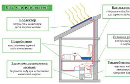
How does a heated floor system work?
Conventional radiators, which have recently been the only possible installations for heat transfer in the house, are gradually being replaced by warm floors and ceilings. They can operate using electricity or hot water. The second option is considered more practical and, if desired, you can construct a water heated floor with your own hands. There is nothing complicated about the heating system. Its scheme includes several elements:
- Water heating boiler. It should heat the water well enough, distributed throughout all the pipes, and still have some power reserve. If this is expressed in numbers, then the additional productivity should be equal to 15-20% of the total capacity of heated floors.
Advice. When you plan to heat a room larger than 120 m², it is advisable to purchase a boiler with a built-in circulation pump or install it separately.
- To avoid having to drain water from the entire system during repairs or in the event of an accident, shut-off valves are installed at the inlet and outlet of the boiler.
 Water heated floor
 - Pipes, which can be polypropylene, or can be made of special cross-linked polyethylene, for distributing water and pipes for laying out the floor surface. The diameter of these pipes must be at least 16-20 mm, and they must also withstand temperatures up to 95°C and a pressure of 10 Bar.
- The collector is a splitter with taps. This is a necessary element to which several circuits are connected from the central supply line of warm water and the return intake of already cooled water.
How does the collector work?
A manifold is a kind of center of pipes, valves, pressure gauges, fittings and other auxiliary components made of metal or plastic. The device performs the function of a mixer of technical water, which comes from the heating circuits. It also distributes the coolant back through the pipes.
As a result of the operation of the collector, the water temperature in different areas is equalized and, accordingly, the air in heated rooms is stably heated.
Any heating system works according to the following principle: process water heated in the boiler is sent through connected circuits and pipes. During their passage, it cools down and, with the help of a circulation pump, returns to the collector through the return line, where it mixes with the hot coolant. The ratio of hot and cooled water is regulated by special valves, and temperature and pressure are monitored by sensors.
 Collector
 The temperature in conventional radiators is 70-95°C, and in a heated floor system it should be 30-50°C. If it increases, deformation of the floor covering and drying of the air in the room may occur. Walking on a hot floor will also be impossible.
It is precisely in such cases that the work of the collector is required, because the boiler is capable of producing coolant of only one temperature.
When the sensor detects an increase in temperature, the valve closes and hot water flows in smaller quantities. After the coolant has cooled, the valve opens again. Cooled process water from the return pipe is supplied under pressure, and hot water from the boiler is supplied as needed.
Components of a heated floor collector
- Mixing valve.
- Balancing valves and shut-off valves.
- Pressure gauge and temperature sensor.
- Circular pump.
- Automatic air vent.
For self-assembly you will definitely need various fittings, adapters, nipples, etc.
 Reservoir components
 Self-assembly of a polypropylene manifold
To assemble the collector you will need:
- ball valves, preferably American;
- pipes with a diameter of 25 and 32 mm;
- couplings with internal thread 32x"1" and 25x3/4;
- couplings with external thread 25x3/4;
- plugs Ø32 mm;
- tees of suitable diameter;
- sealant, preferably thread sealant;
- security group;
- automatic air vent device.
Installation diagram
The distribution manifold consists of two parts. The first part receives heated process water coming from the boiler, and the second part receives the already cooled coolant, that is, the return flow.
- All parts that make up the comb are connected using high-temperature treatment with a special soldering iron for plastic pipes.
- An automatic air vent and a safety group are connected to one part of the collector.
- A tap is connected for emergency drainage of water.
- A tap and an air vent are placed on the second part of the manifold. Pipes will be connected here to return the cooled coolant.
- A circulation pump is connected to the return line, which creates pressure and the coolant begins to forcefully move through the pipes and heating circuits. It is mounted approximately to the boiler, that is, the arrow on the pump should be directed towards the boiler. This installation will allow the device to last much longer.
Advice. To save fuel, it is better to install a three-way valve after the circular pump.
The places that were intended for soldering the tee should be left on both combs and only after accurately determining where it will be located will it be possible to weld the plugs. The presence of a tee is necessary if in the future there is a need to expand the comb.
In order for process water to circulate in the system in the correct direction, it is necessary to install a so-called “reverse” valve.
 Collector installation diagram
 After completing the installation of the heating circuit, you need to connect both collectors to it and install the boiler in the location planned for it. Next, you need to screw one tap into both parts of the collector. The expansion tank is soldered on the supply side. The installation is completed by connecting the heating boiler to the collectors.
Advice. If the house in which the collector is installed has two floors, then it would be reasonable to connect four heating circuits to its terminals, respectively, two for each floor.
Warm floors create a special atmosphere in the house, and the installation of such a heating system should be taken very seriously. Before assembling it yourself, you need to carefully consider every little detail and review the various variations. If there is any error in the calculation, then further operation and maintenance of the system as a whole will become impossible and everything will have to start again.
Warm water floor: video
When using autonomous heating in a private home, situations sometimes arise when the system is not efficient enough. Such a problem, in which all elements of the system are correctly designed and installed, but the temperature in the house does not reach the required level, is extremely unpleasant and requires a solution.
The most suitable solution to this problem is to install a distribution manifold. Such collector groups for heating can be purchased ready-made, or you can save money and make them yourself. How to make a heating distribution manifold with your own hands will be discussed in this article.
Purpose of the heating manifold
In any heating system, one important rule must be observed - the diameter of the pipe leaving the boiler must match or be slightly less than the total diameter of all circuits connected to this boiler. Failure to comply with this rule consistently leads to uneven distribution of the coolant.
For example, we can consider a system to which three separate circuits are connected:
- Radiator heating;
- Warm floor;
- Indirect heating boiler providing hot water supply.
The diameters of the nozzles at the outlet of the boiler and at the inlet of each of these consumers may be the same, but the total value of the latter will be an order of magnitude greater. As a result, a very simple phenomenon arises - the boiler, even if it operates at full capacity, is simply not able to simultaneously ensure the operation of all circuits connected to it. Because of this, the temperature in the house decreases.

Of course, you can try to use all circuits in turn so that they do not load the boiler at the same time. In theory, such measures seem possible, but in practice they turn out to be nothing more than half measures - after all, constant “juggling” with contours cannot be called an attribute of comfortable living in the house.
To get rid of such problems, you need to install a distribution manifold in the system. Typically, stainless steel pipes are used to make such collectors, but other options can be used - for example, polypropylene heating collectors are often found.
The design itself is a device with a set of pipes for the inlet and outlet of the coolant, as well as its separation into separate circuits. All operating parameters are adjusted using shut-off valves, which are included with any manifold.

The main function of the distribution manifold is reflected in its name - it distributes the coolant into separate circuits, and the intensity of its supply can be adjusted at each branch pipe. The result is several circuits that are completely independent from each other, each of which operates in its own temperature regime.
Of course, there is always the opportunity to simplify your work and purchase a ready-made collector, but this solution has disadvantages. Thus, the production of heating collectors at a factory simply cannot take into account the characteristics of each heating system, so you will have to compensate for the characteristics of the collector with additional elements - and this is extra costs. Homemade devices may not be as versatile as factory ones, but they are much better suited for arranging individual projects.
Collector device
Both the factory metal and homemade polypropylene manifold includes two parts:
- The first element ensures the connection of the supply pipe leaving the boiler with the supply pipes of the heating circuits, i.e. this part of the collector distributes the heated coolant. This element of the collector is also important because it allows the circuits to be made independent, which simplifies their maintenance and repair. If there is a collector, to repair one of the circuits, it is enough to close the corresponding valve, which will stop the flow of coolant into this pipeline.
- In the second part of the collector, pressure regulation in each circuit is ensured, due to which the intensity of coolant circulation is determined. The efficiency of all heating systems directly depends on the correct setting of the movement of hot water in the mains.

Inexperienced craftsmen very often build a set of additional elements into the system, believing that these devices will be able to optimize the heating operation. In most cases, such a solution turns out to be useless, because a lack of understanding of the reason for the decrease in heating efficiency does not make it possible to competently intervene in the heating operation. A self-assembled polypropylene manifold often turns out to be the most necessary, optimal solution to the problem of reduced heating heat transfer.
Designing a homemade collector
The first stage of work on creating a homemade distribution manifold is its design. A well-designed project will significantly simplify the work and allow you to create a high-quality welded heating manifold that is optimally suited for specific operating conditions.
Before assembling a heating collector, you need to evaluate a number of parameters of the building’s heating network:
- The number of heating circuits to which coolant must be supplied;
- Number and parameters of heating equipment (power, heating temperature, pressure, etc.);
- The need and possibility of further integration of additional elements into the heating system;
- Number of additional system elements (pumps, valves, shut-off valves, etc.).

- Electric and gas heating boilers can be connected to the collector from above or below;
- If there is a circulation pump in the heating system circuit, boilers can only be connected from the end of the collector;
- Indirect heating boilers and solid fuel boilers can be inserted into the manifold only from the end side;
- The supply of each heating circuit is connected to the manifold from above or below.
In order to accurately and clearly see how to correctly assemble a heating collector, it is worth drawing its design on paper or printing it out if the diagram was created on a computer. The presence of a clear image in accordance with the scale and the required number of elements makes it possible to check during work to prevent installation errors.
On the diagram it is necessary to indicate the dimensions of each part of the collector. For example, the distance between the supply and return pipes should be about 10-20 cm - deviations up or down will complicate the maintenance of the device. A similar distance should be between the supply and return parts of the manifold.

The main quality of a collector is functionality, but one should not forget that the device must be quite compact and decent-looking. That is why, if it is possible to make the device more accurate, it is worth making an effort.
DIY comb assembly
The collector assembly technology includes the following steps:
- In accordance with the dimensions specified in the project, the required amount of materials is prepared;
- The pipes are connected to each other as specified in the project;
- All pipes must be connected to each other using a suitable tool;
- The pipe connections must be thoroughly cleaned and treated with sealant;

- A manifold assembled by yourself must be checked for leaks by closing all pipes except one and ensuring the supply of water to it - the absence of leaks in the closed pipes indicates that the device has been assembled correctly;
- The finished distribution manifold is painted and dried;
- After the paint has hardened, the device can be installed in the location chosen for it.
Conclusion
You can create a distribution manifold comb for heating yourself without any problems. To complete this work, you only need to properly prepare, make a design for the device in advance, and then carefully and carefully carry out all the necessary assembly stages. A correctly assembled collector will fully perform all the functions assigned to it.
When designing heating and plumbing systems, it is often necessary to break down the number of fluid flows. For example, in heating systems with several circuits it is simply impossible to do without coolant distribution. One of the means to achieve the goal is a distribution manifold.
A manifold is a device for distributing liquid, which is often called a comb, apparently due to the external similarity of the manifold circuit with this object. In plumbing systems it is intended to distribute water, for example, from a supply pipe to several taps without loss of pressure.
Accordingly, if two people, for example, use water in the bathroom and in the kitchen, the pressure in the pipes and the water pressure will be equal for both.
The collector simplifies the distribution of water to different places; you can easily make connections to a washing machine, bathtub, sink, or drain tank. There is one target pipe from the collector to the consumer without unnecessary wiring and soldering, which not only simplifies, but also increases the reliability of the system.
In heating systems, combs are used to distribute coolant along circuits; heating is usually divided into sections. For example, the first circuit is a radiator heating system, the second is a warm floor on the same floor. In this case, it is necessary to distribute the coolant from the heater to the circuits and create a return closed system.
Without a collector, such a design will be extremely complex, it will require much more effort and material in order to implement heating, it will be labor-intensive to maintain and less reliable in operation.
The collector distributes the coolant with uniform pressure and returns the coolant from all circuits back to the heater. This method makes the closed system simple and reliable.
It is important! The main factor in the performance of the comb is that the inlet hole for the liquid must have a diameter equal to or larger than the outlet holes.
Characteristics of polypropylene collectors
Polypropylene is non-toxic and, during normal use, completely harmless to both the user and the environment. The material can only release harmful vapors when burning. The melting point of polypropylene is 160 – 170 ºC.
A warm water floor system can be considered a successful alternative to conventional radiator heating or a good addition to it. It can be designed for the entire building or just for one room. In any case, this will be an autonomous system that requires certain preparation of the coolant entering the heating circuit.
This is exactly the role played by the collector for a warm water floor. This is a rather complex device that performs several functions at once. How does it work and connect correctly? Let's try to figure it out.
A warm water floor is an independent heating system, which must be connected to the main one. For this, a collector or several such devices are used if several heating circuits are installed. The simplest manifold is a piece of pipe to which other pipes are connected.
A manifold for a warm water floor is a rather complex device designed to direct and regulate coolant flows
One end of the device is connected to the return or pressure (supply) pipe, it depends on the purpose of the collector. The heating pipes of the water floor are connected to the additional terminals.
Such systems are quite rare in practice; they have been replaced by more complex designs. Today, a manifold for a heated floor is a technological unit that includes several elements. Its main function is to direct and regulate coolant flows.
The heating device is capable of heating the coolant to 75-90C. This is normal for radiators, but unacceptable for heated floors. If a coolant with such a temperature enters its pipes, it will be extremely uncomfortable for a person to be in the room. In addition, the floor covering may be damaged.
That is why a collector is installed, which equalizes the temperature of the return and forward flows, controls the operating parameters of the system using sensors and ensures uniform heating of each section of the pipes. For maximum efficient operation, the distribution manifold is equipped with the following functional elements:
- return and feed combs;
- three or two way valves;
- circulation pump;
- flow meters;
- thermostatic valves.
The device operates as follows. The two combs are interconnected and connected into a common collector block. The return and supply flows are mixed in a special mixing unit, and the temperature of the coolant is also adjusted.

Depending on the purpose and number of heating circuits, the collector circuit may change. A general version of equipment assembly is shown in the figure.
A pumping group is connected to the combs, which ensures fluid circulation through the pipelines. After the temperature sensor reports that the set temperature has been reached in the heated room, the valves automatically shut off the flow of hot water into the system supply line.
Mixing valves
Depending on the desired result, there may be many connection schemes. Any of them must use mixing valves. The devices are designed for mixing cooled and hot liquids. The first comes from the heating circuit, the second from the boiler.
The system can be controlled manually or automatically, which will require additional installation of a control device or servo drive. There are two types of mixing valves.
Two-way elements
Such devices are sometimes also called feed valves. Their main difference from standard valves is the ability to pass liquid in only one direction. If reverse installation is incorrect, the two-way valve will not work correctly and will quickly fail.
A ball or a specially designed rod can be used as a locking element. Thus, adjustments are made either by rotating the ball around its axis, or by moving the rod. To carry out such movements, pneumatic or electric actuators connected to sensors are used.

A two-way mixing valve allows liquid to flow in only one direction, increasing or decreasing the amount of heated coolant as needed. At the same time, its throughput is small, so adjustments occur very smoothly
The most common option is a thermostatic head equipped with a liquid sensor. It constantly monitors the temperature of the coolant entering the heating circuit. Depending on its readings, the head closes or opens the valve, as a result of which the supply of heated coolant moving from the heating device is stopped or resumed.
Thus, liquid is constantly supplied from the return, and from the boiler only as needed. Its quantity is regulated by a two-way valve.
The operating principle of the device explains the main advantage of a manifold equipped with a supply valve. A warm floor with such a collector never overheats, which significantly extends its service life. The low throughput of the two-way valve allows for smooth adjustment of the coolant temperature; sudden jumps are simply impossible here.
Feed valves are easy to maintain and install, as well as reliable in operation. They are very often included in the collector circuit, but have limitations in use. It is not recommended to install two-way valves in systems operating in rooms larger than 200 square meters. m.
Three-way devices
The three-way element is designed differently. It combines the functions of a balancing bypass valve and a bypass feed valve. The element is a housing with one outlet and two inlets. For adjustments, either a ball rotating around an axis or a rod moving vertically is used.
The peculiarity of the three-way valve is that the control element does not completely shut off, but redistributes the incoming liquid flows, thereby mixing them.

A three-way mixing valve, unlike a two-way valve, never completely shuts off the flows entering it. It only redistributes them, through which mixing occurs
Temperature control is carried out automatically, for which the valve is equipped with a drive system that receives information from various sensors. Most often, three-way devices are equipped with servos, which are controlled by weather-compensating controllers or thermostatic elements.
The servo drive activates the shut-off element, which is installed in the desired position to obtain the required ratio of the amount of hot coolant and return.
Weather-dependent sensors are necessary to change the power of the underfloor heating system depending on the weather. For example, with a sharp cold snap, the room will cool down much faster, and accordingly the heating system will have a much more difficult time doing its job.
To simplify her task, it is necessary to increase the coolant flow and its temperature. The disadvantages of three-way valves include their large flow capacity. Under such conditions, even a small shift in valve adjustment will inevitably lead to a significant change in the temperature of the coolant in the circuit.
Another drawback is the possibility of sudden temperature changes in the coolant. It is likely that the valve, triggered by a signal from the thermostat, will allow coolant heated to 95C into the underfloor heating system. Such jumps are unacceptable for the heating circuit, which may not withstand excess pressure and burst.
Three-way valves are used for manifolds installed in rooms larger than 200C and for systems with multiple circuits. In addition, they are indispensable for structures equipped with weather-sensitive controllers that determine the required floor temperature taking into account external conditions.

The operating principle of the underfloor heating manifold is shown schematically in this figure.
Where are the collection departments located?
For a heated floor system, you can install one common collector or install an individual device in front of each heating circuit. In this case, each collector must be equipped with thermostats, a flow meter and three main elements:
- A mixing valve that determines the degree of heating of the coolant in the heating circuit.
- Radiator balancing shut-off valve connecting the collector to the heating system. Opens and, if necessary, closes the water supply to the circuit.
- Overflow valve. It is responsible for constant pressure in the pipes, for which it directs excess coolant into the bypass.
Assembly schemes can be very different. For a system with one radiator pipe, for example, a bypass is required. Moreover, it must always be open, so excess hot coolant will be discharged directly to the radiator.
If there is a return circuit, a bypass is not necessary. If the heated area is small, the collector compartment can be placed in the secondary circuit.
Rules for choosing a collector
You can assemble a manifold for a warm water floor with your own hands or buy it ready-made. In the first case, it is important that all components are produced by one manufacturer. Some companies produce unique connecting elements that do not fit with parts from other suppliers, which threatens the assembled assembly with loss of tightness.
In the second case, when choosing equipment, you need to take into account several important points. First of all, you need to decide on the material from which the collector is made. It could be:
- copper;
- steel;
- brass;
- polymer.
In addition, collectors differ in the number of connected circuits, the number of which can vary from 2 to 12. The choice of device is based on an accurate calculation of the main parameters of the system and the required additional functions. Be sure to take into account:
- number of heating circuits, their length and transmission capacity;
- maximum pressure;
- ability to add branches;
- the presence of elements that automatically control the operation of the device;
- amount of electricity consumed;
- internal diameter of the collector.
The latter indicator should be selected so as to ensure maximum coolant flow in all heating circuits. The efficiency of the unit largely depends on the laying pitch, diameter and length of the pipes included in the heating circuit.
At the system design stage, these parameters must also be calculated. This is a rather labor-intensive undertaking that is best left to specialists. You can make the calculation using a special calculator program that can be found on the Internet.

The collector will work most efficiently if heating circuits of equal length are connected to it. To do this, you may have to split too long branches into several short ones.
When making calculations, it is very important to take into account all system parameters. Otherwise, it will work unproductively: there may be insufficient coolant circulation or leakage, and a “thermal zebra” may also appear, as experts call uneven heating of the surface.
To correctly determine the length of the circuit and the pipe laying pitch, you will need the following data:
- type of finishing floor covering;
- area of the room with a plan for the arrangement of large furniture and household appliances;
- pipe diameter and material;
- heating boiler power;
- type of thermal insulation used.
When making calculations, we must take into account that there should be no pipe joints in the circuit, since the use of couplings and connections under a concrete screed is strictly prohibited. In addition, we take into account the hydraulic resistance of the coolant, which will increase with each turn of the branch and as its length increases.
It is optimal if only circuits of equal length are connected to one collector. Perhaps the best solution for long branches is to divide them into several small ones.
At the design stage, the location where the collector group will be installed should be determined. Most often, it is mounted in a special cabinet, which must be of sufficient size to accommodate all the elements. The equipment is installed at a certain height from the floor near the main pipes.
In this case, you need to place the cabinet so that there is free space for bending the pipes suitable for the manifold. It is desirable that it be placed at the same distance from all heating circuits. If desired, the cabinet can be mounted in a specially made niche or simply attached to the wall.

The figure shows a diagram of the collector assembly. This is how the manufacturer completes the equipment
Assembling a complete manifold for underfloor heating is quite simple. However, before starting work, you should carefully read the instructions, which the manufacturer necessarily includes in the packaging of the equipment. All operations should be performed in strict accordance with its recommendations.
In general terms, assembly is carried out in the following sequence:
- We remove the tubes intended for return and supply coolant from the packaging. They should already be equipped with flow sensors and valves. If the collector is divided into several sections, twist them together.
- We fix the assembled pipes on standard brackets, which will allow you to continue working with greater convenience. The distributor is now a single unit.
- We install shut-off valves, connecting elements, plugs and control devices in place.
- We fix the collector to the wall. You can find recommendations that suggest first installing a valve and a circulation pump. However, in this case it will be very inconvenient to subsequently attach the assembled unit.
- We install a circulation pump and a valve with a servo drive and a thermal head in accordance with the selected scheme.
- We connect the pipes coming from the heating boiler to the unit, and we connect the pipes from the heated floor circuits to the outlets.

The manifold for heated floors is best mounted in a cabinet specially designed for this purpose, which can be “recessed” into the wall or simply mounted on it.
All commissioning work should be carried out before the concrete screed is poured. This is necessary to ensure the tightness of all joints made. We configure the collector.
We check the operation of all control devices that allow you to set the desired floor heating mode, as well as adjust the coolant flows in each circuit.
How to make a collector with your own hands?
Factory-made equipment is quite expensive. Therefore, some home craftsmen decide to assemble the collector themselves. True, it will not be possible to completely manufacture it; some elements, such as a mixing valve, circulation pump and shut-off valves, will still have to be purchased.
The easiest way to assemble a homemade manifold is to solder it from fittings and polypropylene pipes. To work, you will need sections of PPR pipe of the required diameter, usually 32 or 25 mm, as well as bends and tees of the same size. In addition, you need to prepare the valves.
The number of taps and fittings depends on the number of heating circuits. You will also need a special soldering iron for polypropylene parts with various nozzles, a tape measure and scissors. First, we mark the future collector. To do this, we measure and cut pipe fragments, and we do this so that the distance between the tees is minimal.
Otherwise, the part will be too bulky and unaesthetic. Then we weld transitions and taps to the tees. We attach the remaining fittings to the finished manifold, with which it will be connected to the pump.

A homemade manifold for heated floors can be assembled from polypropylene pipes. You need to understand that only the simplest models can be mounted in this way, which will have to be controlled manually
You need to understand that a collector assembled in this way will have a number of disadvantages. First of all, there will be no thermostatic valve on the supply pipe, and there will be no flow sensors on the return pipe. This will lead to the fact that the system will need to be adjusted manually, which is not very convenient and ineffective.
Of course, all these elements can be purchased and installed on the collector. But then the cost of the product will be quite comparable to ready-made equipment made of plastic, which makes its independent production pointless.
As practice shows, the collector can be assembled with your own hands. However, it is advisable to do this only for the simplest models. It is better to buy complex devices ready-made.
One more nuance. Homemade manifolds usually have many joints. No matter how hard the master tries to perform them with the utmost quality, the specific nature of the device’s operation is such that they will definitely leak. Regular repair work, which will inevitably be carried out for a homemade collector, significantly reduces its service life.
Therefore, you should think carefully before deciding to manufacture equipment yourself.

A factory-assembled manifold for heated floors is a reliable device that is indispensable for multi-circuit systems and structures with automatic control
The manifold for heated floors is one of the irreplaceable elements. Without it, a system, especially one that includes several heating circuits, will not be able to provide the required quality of heating or even simply will not be able to function.
Installation and connection of the collector group is the most crucial and difficult moment in the process of installing a heated floor system. Such work requires certain skills and special knowledge. You can do them yourself, but there is a high risk of making mistakes. If you are not confident in your abilities, it is better to trust qualified specialists.
If you decide to install a heated floor yourself, then you will inevitably be faced with the question of how to connect it correctly so that it is operational and heats the floor and the entire room. If you imagine this whole process, you can see that the key to the effectiveness of the system is the correct connection of the heated floor collector, which is responsible for regulating the temperature.
The collector looks like an ordinary piece of pipe with several holes on one side that serve as exits. A couple of such simple structures are actually responsible for controlling the water heated floor. Let's figure out why these outputs are needed and how to connect the underfloor heating manifold.
How does the collector work?
Water floors are laid in various ways, for example, concrete or flooring, but regardless of the technology chosen, it is necessary to purchase and install a manifold cabinet.
In the future, two pipes will be inserted into it:
- supply, which leaves the boiler and supplies hot coolant to the system;
- return, which performs an absolutely opposite role: it serves to collect water that has already been used and has had time to cool. She is returned back to, and the process is repeated again.

The cyclical nature of the process is ensured by another built-in component of the system - a circulation pump. One way or another, during the operation of a heated floor, say during repair work, the system has to be turned off. To do this, each of the pipes is equipped with shut-off valves. A plastic pipe and a metal shut-off valve are connected to each other through a compression fitting. Then a comb is connected to the valve, mounting an air vent on one end and a drain valve on the other. After assembling the cabinet, they proceed directly to installation. And only with a comb already installed on the wall can you cut the circuit pipes to length.
On a note
To ensure the tightness of the connection, the pipes are cut strictly at a right angle.
Simplified diagram of a heated floor collector

The simplest comb circuit consists of two circuits. For the manufacture of the distribution system, brass or stainless steel is used - two materials with high resistance to the aggressive effects of hot water. The comb must be positioned strictly vertically on the wall to ensure the efficiency of all components and allow the coolant to be evenly distributed.
The shut-off valves installed in each circuit may have a manual or automatic opening system using electromechanical actuators. In the system we are considering, as a rule, manual ones are used. 
With the help of these valves, one of which is installed at the inlet and the other at the outlet, the supply of hot water is controlled. To regulate the fluid flow between circuits located, say, in adjacent rooms, so-called balancing valves are installed in the return ridge.
Often the locking mechanism is supplemented with flow meters, which serve as an indicator of coolant flow. Thanks to them, it is possible to adjust each circuit of the system, since flow meters configure and measure the volume of coolant for each of them separately. This is especially important for circuits with different pipe lengths. Thermal sensors are installed on the return ridge, which are necessary to completely or partially shut off the system. This is done automatically using electric servos or manually.

As a rule, there are no problems when installing a simplified system yourself. When installing double-circuit heating, say, to heat a bathroom and toilet, there is no need for expensive equipment. Depending on which mixing valves are used, the ridge patterns become more complex.
Mixing valves

When connecting the manifold, two types of mixing valves are used: two-way and three-way. They are designed for mixing liquids: hot, which comes from the boiler, and cooled, respectively, from the heating circuit. They are controlled manually or automatically - requiring additional installation of a servo drive or control device.
Three-way ones are used, as a rule, for collectors intended for heating large rooms with an area of more than 200 square meters. m. Such schemes also include weather-dependent sensors, which are programmed to determine the required floor temperature based on external conditions.
Two-way ones are used for rooms with a smaller area - less than 200 m2. In such a scheme, the floor temperature is controlled by a valve. If necessary, he himself adds hot liquid coming from the boiler or, conversely, water from processing. If the collector is configured correctly, overheating of the floor is completely eliminated. Two-way valve circuits provide smooth and stable adjustment.
There are many other collector schemes and installation types.
Control elements
Setting up a heated floor collector is impossible without special devices. With their help, the optimal heating mode of the system is established and water flows in the pipelines are regulated. Each of them performs a specific function.
- Water temperature sensor
Installed on the inlet and outlet pipes of the device. These devices do not affect the operation of the system, but indicate the current heating rate. The difference in values can be useful in calculating operating efficiency. They also serve as an indicator of heating mode violations.
- Central thermostat with servo mechanism and sensor.

It is mounted on the inlet pipe of the inlet manifold and connected to the return pipe with cooled coolant. The temperature sensor is placed in the comb body. There is a rotary knob on the body of the thermostat with which you can set the required temperature level. The device receives readings from the sensor about the degree of water heating. Depending on this, the flow of cold and hot coolant is regulated.
- Servo drives on the inlet comb nozzles
According to the principle of operation, they are completely similar to a thermostat, but with minor additions. With their help, the volume of water flow for each circuit of the water floor is regulated. Depending on the model, this can be done in manual or automatic modes. For the latter, servos with built-in temperature sensors are used, which can be connected to a common remote thermostat.
- Flow meters
Devices that are optional for installation, but which, however, can become effective elements for manually controlling the operation of a water heated floor. They are installed on the return manifold pipes and are locking mechanisms with a glass bulb.

When you turn the head on the body, the rod in the device changes its position. This affects the volume of liquid passing through it. For clarity, a measurement scale is printed on the surface of the flowmeter, indicating the flow rate of water l/min.
Connection rules
In most cases, a ready-made manifold is purchased, in which all elements are selected according to technical characteristics. If you have experience in assembling such structures, you can assemble the device yourself. How to properly connect a heated floor, take into account the parameters of the overall heating system and the technical properties of the combs? To do this, you must follow certain installation rules.
Attention
First, it is compiled, which indicates the dimensions of the pipes, where they are laid and connections with heating. The throughput capacity of each comb must be calculated, their diameter and material of manufacture must be selected. The most commonly used products are stainless steel or copper.
The location of the device is selected based on the following rules:
- The highways should be approximately equal in length.
- The section of the wall where the manifold cabinet for heated floors will be installed must have free access. Furniture or other parts of the interior do not interfere with a full inspection of the device or carrying out preventive or repair work.
- The connection point of the device must be higher than other elements of the system.
A security system must be installed. It consists of an air valve and a bypass. When the temperature of water rises sharply, it expands. The air valve releases excess air, normalizing the pressure in the pipes. A bypass is necessary to quickly shut off water in case of emergency situations.
Once the installation of the collector is complete, the underfloor heating pipelines are connected to it. The quality of the joints, their tightness and reliability must be checked. The system is started before the main covering is installed. By changing the temperature conditions using the control device, the heating quality of each line is checked, and the pipes are inspected for leaks. After this, you can begin installing the flooring.
Royka setting

As a rule, a special balancing table is attached to the diagram, on the basis of which the comb can be adjusted according to two parameters: circuit length and heating load.
The table relates the circuit number and the number of revolutions from the position of the balancing valve - “closed”. Set up the comb like this:
- remove the cap from the valve that serves to protect it;
- close the valve all the way - use a hex key for this;
- determine the number of revolutions for a given circuit;
- turn off the valve to this number;
- The remaining circuits are configured in the same way.
Correct configuration and connection of the collector are necessary for long-term operation and efficient operation of the system.
Exploitation
The layout of a heated floor collector is relatively simple. But during its operation, it is necessary to periodically check the performance of individual elements and the entire system as a whole. To do this, it is recommended to draw up a schedule for checking equipment and carrying out preventive maintenance of the following nature:
- Monitoring the performance of device elements.
- Checking the parameters of the coolant in each of the lines - speed, temperature. To do this, it is necessary to periodically take readings from control devices.
- Monitoring the integrity of the connection of pipelines to the combs, the absence of leaks and depressurization.
- Maintaining the temperature conditions of the system by taking data from thermometers.
By carrying out these simple procedures, you can maintain the uninterrupted operation of the entire system and its individual parts. But the main condition is the professional connection of the heated floor collector. The functionality of the device and its performance depend on the correctness of this installation stage.