Connecting the electrical panel to the house. We assemble the shield in the apartment and house ourselves
In old houses, an electric meter was installed at the entrance with a plug as a fuse. Relatively recently, this satisfied consumers: there were few household appliances and low power. Today, when almost every home has a lot of powerful electrical equipment, a different device for introducing electricity into the house is required.
Electrical panel - why is it needed in the house?
Installation of an electrical panel solves many problems related to the safety of using electricity and its quality. New buildings, as a rule, are equipped with them immediately, and in old buildings, it is advisable to install them instead of the primitive old ones. The shield will distribute electricity among groups of consumers, protect against short circuits and loads exceeding the nominal value.
Electrical appliances are installed in a plastic or metal box. An electricity meter and main switch are required. The meter can be installed independently or by energy company employees. The main switch cuts off the electricity consumption in the apartment if necessary, or it works automatically in an emergency. The meter and the input machine, if installed in front of the meter, must be sealed.
But this is part of the electrical panel devices. Additional convenience and safety in a private home are provided by automatic switches. Their role is reduced to protecting the circuits of the home network - wiring and household appliances. Each machine serves one group of consumers, and separate machines are installed for powerful devices. Each switch is designed for automatic operation or forced shutdown.
The residual current device contains a differential transformer that compares the balance of incoming and outgoing current. If it is broken, which happens when there is an uncontrolled leakage of current or when a person comes under voltage, the protection is triggered. The network with the RCD turns off, and the person does not even have time to feel the electric shock. The protective shutdown is designed for a current that is safe for humans.
In addition to the listed devices, the shield is equipped with tires. The machines are connected to a distribution bus in the form of a copper strip - the input contacts are connected on it. The block with terminals for supplying neutral wires is called a zero bus. The grounding is connected to another bus – the grounding bus.
Consumer groups - how to distribute according to the rules
Electricity entering the house is correctly distributed among consumers. There are rules, subject to which you can assemble an electrical panel with your own hands:
- 1. We separate all consumers with a power of 2 kW and above into separate groups. On each we install an automatic machine designed for a certain load.
- 2. For a washing machine, dishwasher, air conditioner, and other low-power appliances, 16 A circuit breakers are needed. We connect with a cable with a cross-section of 2.5 mm2.
- 3. We connect more powerful devices through a 20 A or 32 A circuit breaker. We take a cable with a larger cross-section: 4 mm2 or 6 mm2.
- 4. We make lines to sockets separately for each room, using 2.5 mm2. In the distribution box we make branches to the sockets.
- 5. For lighting lines we use a 1.5 mm2 cable, each one is protected by a 10 A automatic circuit breaker. We run a separate cable.
Cables to powerful electrical appliances should not have branches, but should be laid in one piece to each consumer separately.
At first glance, the approach to installation with separate cables may seem unnecessary. In fact, it is the only true one, it provides high security and ease of use. In any emergency situation, a group of consumers is automatically disconnected, and not the entire network. It is much easier to find and fix the problem with this wiring diagram.

Electrical panel installation
Electrical panel diagrams - we make it ourselves
To assemble the electrical panel, you need a diagram. To compile it, we take into account all the factors and features of electrical energy consumption at home:
- how many kilowatts of electricity consumption is calculated in total;
- how much power each group consumes;
- how many separate consumer groups are there in total;
- where the electricity meter will be installed.
We draw up the diagram in a clear and convenient form. We indicate device ratings, cable cross-sections, wiring to consumers. Below is shown the approximate internal contents of the panel and the wiring for a single-phase network.

For three-phase network voltage there are no big differences in the circuit. Another principle of consumer distribution is applied: separate groups are connected to separate phases. It is important to maintain load balance between phases.

Components - which shield and modules to choose
The switchboard housing is made of metal or plastic, mounted on the wall or recessed into it. For hidden wiring, a distribution panel hidden in a wall niche is more suitable. The external shield can be installed inside the house or outside. The question of choice is important: a very cheap plastic case quickly becomes unusable. It is better to buy a box that has removable walls, in which the DIN rails can be easily removed or moved aside. In terms of size, it is better to have some reserve of internal space.

The initial element of any circuit is an input circuit breaker, which turns off the supply of electricity to the house. Its ratings depend on the total power consumed by the house. The Decree of the Government of the Russian Federation stipulates that network organizations provide a standard 380 V power supply connection at 15 kW. If more is required, it is connected for an additional fee.
- rated current;
- the current at which the machines operate;
- the speed of their operation.
The machines are installed separately in each circuit. It is important to calculate their parameters: if there is insufficient power, false alarms will constantly occur. With low power, they will not be able to fulfill their purpose - to protect against overload. The machines are equipped with a device for the operation time. Lower down the circuit it should be installed with a shorter shutdown time so that it occurs along the output line.
With a rated current higher than the total current of the automatic devices subordinate to it. Then the machines will turn off earlier, protecting the RCD from damage.
Internal content - layout of modular devices
The equipment mounted in the panel is manufactured according to standard unified dimensions. A DIN rail – a metal profile – is used for mounting. The single space occupied by a single-pole circuit breaker is called a module. To calculate how much space is needed in the panel, you should know that a two-pole AV is 2 modules, a three-pole AV is three. A single-phase RCD takes 2 modules, a three-phase one - 4. One terminal block - one module, a counter, depending on the modification, - 6-8 modules.
It is carried out on a table, which is much more convenient than on the wall. But first you should install the mount for the shield when it is not yet filled with modules. The implementation of the circuit diagram can be carried out in several ways: linear or group. Regardless of the method, the opening machine always comes first. According to the linear principle, all RCDs are located further, followed by automatic machines. The placement is simple, but the fault is difficult to find. According to the second method, devices are placed in groups: first the RCD, then the machines in its group.
Installation rules must be followed:
- connections inside the panel are made with a wire of the same cross-section as the input one;
- the entrance is located at the top, the exit at the bottom;
- It is prohibited to clamp a stranded wire without NShVI lugs;
- To clamp different conductors in one terminal, use lugs for two wires.
Let's start assembling. We arrange the modules according to the chosen scheme on the DIN rail and secure them with clamps. To make it easier to work, in addition to the diagram, we draw up a plan for the location of the devices. Then we connect them together with wires. We clean the ends; if the wires are multi-core, we insert them into NVSHI lugs of a suitable cross-section. We crimp the tips using KVT press pliers, which are not very expensive. It is this tool that will securely secure the conductors in the lugs.

The use of special tires (combs) will greatly facilitate the disconnection of the electrical panel. They are equipped with flat contacts (pins), which are inserted into the automation contacts, ensuring a reliable connection. Manufacturers of automatic devices produce combs that are suitable in size specifically for these modules; they may not fit others due to differences in pitch.
You should buy all circuit breakers, automatic circuit breakers, RCDs, and buses from the same manufacturer, which will greatly facilitate installation, and the panel will look beautiful and compact.
Connecting cables - entry and termination inside the panel
Correct cable entry greatly simplifies installation and allows for optimal organization of the internal space. You should buy shields that have technological holes for entry, otherwise you will have to cut or drill them. Good shields have plugs that we remove and install the cable. We connect it to the input machine and secure it with a plastic clamp. We mark all cables at once.
Surface insulation on the input is not needed, so carefully, so as not to damage the insulation of the conductors, remove it. It is more convenient to work with individual wires than with a rigid cable. We distribute all the wiring in the panel in bundles: separately phase (L), zero working (N) and protective zero (PE). We strive to ensure that they overlap as little as possible. We pre-mark the ends and tighten them with clamps.

When bringing the cable inside the shield, we leave it a length that is twice the height. This is done like this: stretch the cable to the connection point, stretch it again to the inlet hole and cut it off. This is not superfluous at all: the wiring follows its own trajectory, and not the shortest path. When you have to pull them to reach their destination or build them up, this is bad. So it’s not worth saving a few ten centimeters.
Commissioning and operation of the electrical panel
After installation is complete, turn off all devices in the panel. We load all sockets. We apply voltage, check the presence at the input, the correct phase and zero. Using the “Test” button, we check the RCDs and automatic circuit breakers one at a time. We check the voltage at the input of the machines, turn them on one at a time and check the output voltage. We turn on powerful devices, monitor the condition of the shield: there should be no sparkling, smoking, or heating. We check sockets and lighting.

The electrical panel should be inspected periodically. We will definitely open it in a month and tighten up all the contacts. In the future, we check the operation of the RCD monthly. If the installation is carried out in compliance with the recommendations of specialists, thoughtfully and without haste, the equipment will serve for a long time and reliably.
The comfortable living of all its inhabitants and the uninterrupted operation of household appliances depend on the correct connection of electrical wiring in the house. Do you agree? To protect the equipment in the house from the consequences of overvoltage or short circuit, and the inhabitants from the dangers associated with electric current, it is necessary to include protective devices in the circuit.
In this case, it is necessary to fulfill the main requirement - the connection of the RCD and circuit breakers in the panel must be done correctly. It is equally important not to make a mistake when choosing these devices. But don't worry, we'll tell you how to do it right.
This article will discuss the parameters by which RCDs are selected. In addition, here you will find features, rules for connecting machines and RCDs, as well as many useful connection diagrams. And the videos given in the material will help you put everything into practice, even without the involvement of specialists, if you have at least a little knowledge of electrical engineering.
To connect the RCD in the panel, two conductors are needed. Through the first of them, the current flows to the load, and through the second, it leaves the consumer along the external circuit.
As soon as current leakage occurs, a difference appears between its values at the input and output. When the result exceeds a predetermined value, it is triggered in emergency mode, thereby protecting the entire apartment line.
Residual current devices are negatively affected by short circuits (short circuits) and voltage surges, so they themselves need to be covered. The problem is solved by including automata in the circuit.
The current powering electrical appliances flows through one of the core windings in one direction. It has a different direction in the second winding after passing through them.
Independent installation of protection devices involves the use of diagrams. Both modular RCDs and machines for them are installed in the panel.
Before starting installation, you need to resolve the following issues:
- how many RCDs should be installed;
- where they should be in the diagram;
- how to connect so that the RCD works correctly.
The rule of electrical installation is that all connections must go into the connected devices from top to bottom.
Professional electricians explain this by saying that if you start them from below, the efficiency of the vast majority of machines will decrease by a quarter. In addition, the foreman working in the switchboard will not have to further understand the circuit.
RCDs designed for installation on separate lines and with low ratings cannot be installed in a general network. Failure to comply with this rule will increase both the likelihood of leaks and short circuits.
Selection of RCD according to main parameters
All technical nuances associated with the choice of RCDs are known only to professional installers. For this reason, specialists must select devices when developing a project.
Criterion #1. The nuances of selecting a device
When choosing a device, the main criterion is the rated current passing through it in long-term operating modes.
Based on the stable parameter - current leakage, there are two main classes of RCDs: “A” and “AC”. Devices of the latter category are more reliable
The value of In is in the range of 6-125 A. Differential current IΔn is the second most important characteristic. This is a fixed value, upon reaching which the RCD is triggered. When choosing it from the range: 10, 30, 100, 300, 500 mA, 1 A, safety requirements take priority.
Affects the choice and purpose of installation. To ensure the safe operation of one device, they are guided by the rated current value with a small margin. If protection is needed for the house as a whole or for an apartment, all loads are summed up.
Criterion #2. Existing types of RCDs
RCDs should also be distinguished by type. There are only two of them - electromechanical and electronic. The main working unit of the first is a magnetic circuit with a winding. Its action is to compare the values of the current going into the network and returning back.
There is such a function in the second type of device, but it is performed by an electronic board. It only works when there is voltage. Because of this, the electromechanical device protects better.

The electromechanical type device has a differential transformer + relay, and the electronic type RCD has an electronic board. This is the difference between them
In a situation where a consumer accidentally touches a phase wire and the board turns out to be de-energized, if an electronic RCD is installed, the person will come under voltage. In this case, the protective device will not work, but the electromechanical device will remain operational under such conditions.
The subtleties of choosing an RCD are described in.
Installation of RCDs and automatic machines in the panel
The electrical panel, in which the metering and load distribution devices are located, is usually the place for installing the RCD. Regardless of the chosen scheme, there are rules that are mandatory when connecting.
Main rules of connection
Along with the automatic shutdown device, they are also installed on the shield. All you need for this is a minimum of tools and a competent diagram.
The standard set should consist of:
- from a package of screwdrivers;
- pliers;
- side cutters;
- tester;
- socket wrenches;
- Cambric.
Also for installation you will need a VVG cable of different colors, selected in cross-section in accordance with the currents. The PVC insulating tube is used to mark the conductors.
When there is space on the DIN block available on the panel, a residual current device is mounted on it. Otherwise, install an additional one.
The key principle of installation is the following: contact of the neutral conductor after the RCD with either the input zero or grounding is unacceptable, therefore it is insulated in the same way as other conductors.
The circuit breaker must be switched on in series with the RCD. This is also one of the most important rules.
When the entire home is protected using one RCD, a circuit that includes several circuit breakers is used.

To eliminate the presence of additional wires on the shield, which does not look very aesthetically pleasing, a comb (distribution) bus is used to connect a bundle of wires
The project includes, in addition to additional AVs, one more component - a zero bus insulator. Mount it on the panel body or on a DIN rail.
This addition is introduced due to the fact that with a large number of neutral conductors connected to the output terminal of the disconnecting device, they simply will not fit in one clamp. An isolated zero bus is the best way out of this situation.
Sometimes electricians, in order to place the entire bundle of neutral wires in the socket, decide to cut the cores of a single-core cable. In the case where the cable is multi-core, several cores are removed.
It is better not to use this option, since due to a decrease in the cross-section of the conductors, the resistance will increase, and therefore the heating will increase.
Both the number of mounting holes and their diameter may vary. The ground bus is attached directly to the body.
Neutral wires in one twist are an additional inconvenience when identifying damage on the line, as well as when you need to dismantle one of the cables. Here you cannot do without unscrewing the clamp and unwinding the harness, which will certainly provoke the appearance of cracks in the veins.
You cannot install two wires simultaneously into one socket. The inputs of the circuit breakers are connected by jumpers. As the latter, during professional installation, special connecting tires called “comb” are used.
Features of connection diagrams
The choice of scheme involves taking into account the characteristics of a particular electrical network. Among the numerous options, there are only two circuits used to connect machines and RCDs in, which are considered the main ones.

The simplest installation diagram for automatic machines and protective devices. It can be used to connect from one to several loads connected in parallel
The first and simplest method, when one RCD protects the entire electrical network, has disadvantages. The main one is the difficulty in identifying the specific location of the damage.
The second is that when some kind of failure occurs in the functioning of the RCD, the entire system will be taken out of operation. The residual current device is allocated a place immediately after the meter.
The next method provides for the presence of such devices on each individual line. If one of them fails, all the others will be in working order. To implement this scheme, a larger shield and greater financial costs are required.
Details about a simple scheme
Let's consider connecting an RCD with automatic circuit breakers to a simple residential switchboard. At the entrance there is a two-pole automatic switch. A two-pole RCD is connected to it, to which there are two single-pole circuit breakers.

There is a “Test” button on the RCD body. It is intended to test its operation. Manufacturers advise using this key at least once a month and checking the operation of the device itself.
The phase supplied to the circuit breaker enters the input of the RCD with output to the circuit breakers. The zero output from the machine goes to the zero bus, and from it to the input to the device.
From its output, the neutral conductor is directed to the second neutral bus. The presence of this second bus contains a special nuance, without knowing about which it is impossible to achieve normal functioning of the circuit.
During operation, the RCD controls both the incoming and outgoing voltage - as much as is at the input, so much should be at the output.
If the balance is disturbed and the output is greater by the value of the setting to which the RCD is configured, it is triggered and the power is automatically turned off. The zero bus is responsible for this process.
In electrical circuits where the installation of a residual current device is not provided, there is only one common zero.
In circuits with RCDs the picture is different - several such zeros are already present here. When using one device, there are two of them - the common one and the one in relation to which the protective device operates.
If two RCDs are connected, there are three zero buses. They are designated by indices: N1, N2, N3, etc. In general, there are always one more zeros than residual current devices. One of them is the main one, and all the others are tied directly to the RCD.

Color designation of electrical wires according to the rules established by the PUE. This marking must be studied before proceeding with the installation of protective devices.
If not all equipment is supposed to be connected through the RCD, then zero is supplied from the common bus. In this case, the residual current device is removed from the circuit.
When adding a single-pole circuit breaker operating from an RCD, the phase from the output of the latter is supplied to the input of the circuit breaker. From the output of the switch, the conductor is connected to one load contact. Zero on it is brought to the second conclusion. It comes from the zero bus created by the RCD.
There is one more element on the shield - a protective grounding bus. Correct operation of the RCD without it is impossible.
Three-wire network is only available in new houses. It must have a zero phase and grounding. In houses built a long time ago, there is only a phase and a zero. In such conditions, the RCD will also function, but slightly differently than in a three-phase network.
As a way out, the grounding is carried out by a third conductor to the sockets, and then to the ceiling to the place where the chandeliers are connected. Ground is not supplied to the switches.
Option for connecting machines without RCD
There are times when one of the machines needs to be connected without bypassing the residual current device. Power is connected not from the output of the RCD, but from the input to it, i.e. directly from the machine. The phase is supplied to the input, and from the output it is connected to the left terminal of the load.
Zero is taken from the common zero bus (N). If a fault occurs in the area controlled by the RCD, it will be removed from the circuit, and the second load will not be de-energized.
RCD in a three-phase network
A network of this type includes either a special three-phase RCD with eight contacts, or three single-phase ones.
The connection principle is completely identical. Mount it according to the diagram. Phases A, B and C supply power to loads rated at 380 V. If we consider each phase separately, then in tandem with cable N (0), it provides a series of single-phase 220 V consumers.
Manufacturers produce three-phase trip protection devices adapted to high leakage currents. They only protect electrical wiring from fire.

The photo shows two diagrams: a trip protection device in a single-phase and three-phase network of the TN-C-S system. This means that the neutral cable is divided into working and protective
In order to protect people from the effects of electric current, single-phase two-pole RCDs are installed on the outgoing branches, configured for leakage current in the range of 10-30 mA. For cover, a machine gun is placed in front of everyone. In the circuit after the RCD, the working zero and ground cannot be connected.
RCDs and circuit breakers on a three-phase switchboard
Let us examine in detail a not entirely standard circuit assembled on a three-phase distribution panel.
It contains:
- three-phase input circuit breakers - 3 pcs.;
- three-phase residual current device - 1 pc.;
- single-phase RCDs - 2 pcs.;
- single-pole single-phase circuit breakers - 4 pcs.
From the first input circuit breaker, voltage is supplied to the second three-phase circuit breaker through the upper terminals. From here, one phase goes to the first single-phase RCD, and the second to the next.

The voltage from the second input circuit breaker is supplied to a three-phase RCD, the lower terminals of which are connected to a three-phase load. This protective device protects against leakage currents, and the second input circuit breaker protects against short circuits.
Single-phase RCDs installed on the panel are two-pole, and automatic machines are single-pole. For the protective device to function correctly, it is necessary that the working zeros after it are not connected anywhere else. Therefore, after each RCD, a zero bus is installed here.
When the machines are not one-pole, but two-pole, then there is no need to install a separate zero bus. If two zero buses are combined, false positives will occur.
Each of the single-pole RCDs is designed for two circuit breakers (1-3, 2-4). A load is connected to the lower terminals of the machines.
The common ground bus is installed separately. Three phases enter the input circuit breaker: L1, L2, L3 and the working neutral wire.
RCD installation details:
RCDs and automatic machines are technically complex equipment. It is advisable to install it in places where electric current can pose a threat to both the safety of people and home appliances.
Its installation requires taking into account many parameters, so both calculation and installation are best performed by qualified specialists.
If you have experience in installing RCDs yourself, please share it with our readers. Tell us what points should be given special attention. Leave your comments and ask questions in the block below the article.
Each house is equipped with an electrical system. The wiring is usually installed from scratch or replaced with a new one. The electrical wiring system must not only distribute electricity correctly, but also be highly safe. The protective function is performed by an electrical panel. It must be installed in every home. Professional electricians perform high-quality assembly of electrical panels, but if certain rules are followed, such work can be done independently.
When creating high-quality wiring, you should understand how the physics of the process is carried out. Engineering knowledge consists of understanding the basics of physics and mathematics. Therefore, you can carry out wiring yourself only if you have full knowledge of certain knowledge. It is important to use specific recommendations and follow certain rules. Requirements for electrical panels are specified in the relevant GOSTs.
What is the shield for?
Several systems can be called an electrical panel. These include the distribution panel, main and group. They all work on the same principle. What is the purpose of the electrical panel? It has several functions:
- It must receive energy from an external source.
- The electrical panel is used to distribute energy to different groups of consumers;
- Another function of the shield is to protect the wiring. It prevents short circuits.
- Modern panels are able to monitor the quality of energy supplied to the consumer and, if necessary, respond to this.
- The electrical panel must guarantee absolute safety and protect people from many damaging factors.

A small device must meet many requirements. This requires a careful and thoughtful approach to working with the electrical panel. Installation of the device will not be complete without carrying out an accurate scientific calculation. However, all complex concepts and processes can be presented in the form of simple recommendations. The basic requirements are specified in GOST.
How is electricity distributed?
Distributing energy among user groups is one of the main tasks of an electrical panel. If you decide to install it yourself, you should know several mandatory distribution rules:


Many may think that this approach to installing the panel and running electrical cables is quite redundant. However, in reality, this method is the only correct one, given the need to ensure the safety and comfort of control prescribed in GOST.
Many inexperienced electricians, unfamiliar with the principles of wiring, purchase small cross-section cables instead of high-quality products in order to save money. In addition, amateurs often purchase RCDs and low-cost automatic devices. Such decisions may affect the safety of the residents of the house in which electricity is installed.

One example should be considered before wiring. A cable with a cross section of 1.5 square meters comes out of the shield. mm, which is protected by a 10 A circuit breaker. It can be intended for lighting in one room. The line goes into a junction box. If in the next room the load on the electrical network is expected to be less, an inexperienced electrician may decide to reduce the cross-section of the cable leading from the junction box to 0.75 square meters. mm.
For unknown reasons, a short circuit occurs in the electrical network. The wires can simply be flooded from above the apartment. The cable begins to experience strong currents, reaching up to 10 A. It cannot withstand it and catches fire. The cable insulation melts, and a fire may start in the apartment. It follows from this that the line should not have a reduction in cable cross-section under any circumstances.

Electrical panel diagram
When installing the panel and electrical wiring, you should draw up the diagram correctly. Such work is usually entrusted to a specialist engineer. However, subject to certain principles, it is performed independently. The wiring diagram and panel must be accurate. This will ensure safe operation of the system.
One of the simplest is the single-line diagram of the shield. You can understand it quite quickly. The name “single-line” appeared because in such a diagram one line denotes a group of wires at once, and not individual electrical cables. How many wires there are are shown using slashes. Below the diagram shows the power, cable type and consumer lines.

To protect the electrical system from overvoltage, circuit breakers are used to open the electrical network under load. It is not recommended to use them everywhere, since they react quite painfully to shutdown under load. It is better to install electric machines.
To understand the connection diagram of the electrical panel with all current consumers, you should look at its more attractive option. This diagram displays all electrical devices and conductors. The electrical panel diagram must meet the requirements of GOST.

The need for an RCD for an electrical panel
An RCD is a device that turns off the power when certain values are exceeded. It is able to detect leaks in the electrical network. It must be installed on all electrical outlets and power lines. You need to know several rules for selecting and operating such a device:

The use of differential automatic machines is not justified from the economic point of view. It is better to buy RCDs and automatic devices separately. You can install a differential automatic machine only if there is an acute lack of free space in the panel. Such a device can also be used to protect particularly important electrical lines.
Advice! After developing the electrical panel diagram, you should consult an experienced electrician. This will avoid many problems in creating high-quality electrical wiring.

Number of seats in the panel
Each device installed in an electrical panel is made in standard sizes. All elements are located in a metal profile. Its width is 35 mm. This width is enough to install a single-line circuit breaker in the panel. The main parameter of the electrical panel is the number of landing modules. To find out how many such places are needed, you should use a special table.
It is better if a modular socket is installed in the panel. It is necessary to allocate 3 places for it. Such a device may be needed when performing repairs. With such equipment, you can easily disconnect all lines and connect a power tool to the panel. To do this you will need an extension cord.

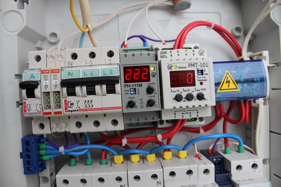
In addition, you should install a voltage relay that will monitor its readings in the network. If the voltage goes beyond the specified limits, the load will be disconnected. After a certain period of time, the tension will appear again. This saves valuable energy consumers.
Even when installing a simple shield, 20 places will be required. However, professional electricians recommend choosing shields with a reserve so that you can add a line later. Therefore, it is better to purchase a shield for 24 or 36 seats.

Choosing a good electrical panel
Once the number of seats has been determined, you should think about the design of the product. There are several types of shields, distinguished by installation method:
- Mounted panels, for which it is not necessary to prepare a special niche. They can simply be hung on the wall using screws or anchors. When installing a shield on the street, you should make it hinged. If it is installed indoors, the wiring must be open.
- Built-in shields- a niche in the wall is prepared for such devices. Such products are installed exclusively in rooms with hidden wiring.
Shields are often made with a metal body. They are manufactured in different types - built-in and wall-mounted. Due to the increased strength of the body, they have a certain advantage over models made from other materials. They are especially often installed outdoors. Such shields are much easier to protect from vandals. Outdoor models are usually equipped with a glass window that allows you to read meter data.
Shields made of plastic are very popular today. They can be wall-mounted or built-in. Such devices are intended for both outdoor and indoor installation. Thanks to the wide variety of models, they can fit into almost all interiors. They usually look very aesthetically pleasing. However, after a few years, the white plastic may turn yellow.

There are several tips on how to choose an electrical panel:
- First you should pay attention to the seller. From a trusted supplier you can immediately purchase an electrical panel and modular equipment, and many components. It is better if the purchase is made in a large store that has a fairly large assortment. These sellers care about their reputation, so they won’t be able to find low-quality products.
- It is also important to consider the manufacturer. Among the world brands we can highlight Hager, Makel, ABB. However, there are also several proven domestic manufacturers.
- Each manufacturer offers shields with different configurations. It is better to choose products with rich functionality. For such a shield, the slats should be in a frame that can be easily dismantled. This design solution simplifies the installation and dismantling of the structure. Additionally, you should choose a shield that has proper organization and locking mechanism for incoming cables. It is better if the shield has cable organizers, which will save space inside the structure.

Many well-known manufacturers also produce related products - locks, combs, doors.
Assembly and installation of the shield
An electrical panel is a complex device that requires precise assembly and proper installation. Do not install modular equipment in a dirty or dusty area where construction work is taking place. It is better for these processes to take place in a clean and well-lit room, on a sturdy table. That is why it is better for the shield to be equipped with a removable frame with slats.
Installation of the shield housing
Hanging structures can be installed in a few minutes. This work is no different from hanging a regular cabinet. Therefore, a built-in design was chosen as an example. The technology for installing it in a brick or concrete wall is no different.
Installing a shield in a concrete structure is a little more complicated. First you should find out whether it is a load-bearing wall or not. In the first case, installing a shield in it is prohibited. Upon approval, it will be necessary to carry out reinforcement according to the new project and carry out various works. This will take a lot of time and financial costs.

It is better if the shield is installed in a false wall. All the necessary cables can be laid in it in such a way as to ensure maximum operating efficiency of the panel. At the same time, the wall will become 10 cm thicker. This solution can be used advantageously from a design point of view.
First, you should consider the rules for assembling an electrical panel with your own hands:
- Shields should be placed in ventilated rooms, placing the structure close to the entrance to the home. It is better if the shield is installed in the vestibule.
- The room in which the shield will be mounted must have a humidity of 60%.
- There must be a distance of at least 15 cm from doorways, corners and slopes to the side surfaces of the shield. In addition, easy access to the device must be ensured. It is not recommended to install shields in cabinets or wardrobes.
- Highly flammable objects and substances should not be placed near the shield.
- Installation should be carried out at a height of 1.4 to 1.7 m above the finished floor.

Installing an electrical panel is a complex procedure that is performed in strict sequence. Each stage of work should be performed as accurately as possible, without missing details. The procedure for installing the housing is as follows:
- Mark the installation location of the shield. To do this, use a level to draw the bottom line of the structure and the vertical of either side.
- Attach the housing to the wall. Align the bottom and side edges with the markings. Outline the body around the perimeter. To do this, use a construction marker.
- Using a grinder, cuts are made along the perimeter of the niche. For this work, a grinder with a diamond blade is used.
- Using a hammer drill, you need to hollow out the entire surface of the niche and then level the bottom.
- Try on the housing in the niche, check how optimal the installation depth is.
- Install the standard mount on the shield, and then insert the shield into the niche, level it and make marks in the wall for the dowels.
- Using a hammer drill, drill holes for fastenings, insert dowels, install the shield and secure it.
- Remove the frame with the slats inserted into it from the shield.
- Fill the space between the niche and the body with polyurethane foam.

Situations often arise when wall mountings are not supplied with the shield. You can install the shield on the dowels, punching them through the back wall. For fastenings there are places in which holes are drilled.
Entering cables into the panel
This procedure requires special attention. With proper organization of cable entry, the installation of modular equipment will be significantly easier. This will allow you to correctly install the necessary devices.

Standard shields are made in such a way that it is convenient to insert cables into them. In the lower and upper parts of such structures there are special perforated holes. To insert the pipe, you just need to press them in with your finger. Typically, such holes are designed for pipe diameters of 16 and 20 mm.
Inserting the cable into the wall-mounted electrical panel is quite simple. The electrical cable only needs to be fixed and methodically insert the cables one by one. When entering a cable into a built-in device, a certain technology must be followed. In this case, the body of the shield must be fixed to alabaster. In addition, it must be leveled. This type of work is best done by a professional.

If you buy a cheap panel, inserting electrical cables will be problematic. You will have to cut the holes yourself. Then you need to install special plates. All difficulties can be avoided if you immediately purchase a more expensive design that meets all GOST requirements.
Another problem that inexperienced electricians face is when introducing an electrical cable into an electrical panel when passing through technological holes; the cable has a certain degree of freedom when moving in the pipe. At the same time, it is difficult to organize the wires in the electrical panel itself. This problem can be solved quite simply - you need to put alabaster in the groove near the place where the electrical cables enter the panel. However, this solution is not very modern and not the most effective.

Pre-assembly of electrical panel
There are many photographs on the Internet that illustrate the assembly of electrical panels already installed in place. In this case, it is necessary to arrange the equipment modularly and perform switching of various elements with wire PV1. Its cross-section should be from 4 to 6 square meters. mm. The equipment is installed at a height of 1.5-1.7 m from the floor. This must be taken into account, knowing that painters and puttyers will be walking around at the same time. In reality, electrical panel installation is very difficult to carry out even for an experienced professional.

Conclusion
Considering all the problems that you may encounter during the work process, it should be recalled that it is better to purchase only high-quality components. Modular equipment must be installed on a table in a clean room. Experience in such work will allow you to connect all lines to an existing panel.
In a modern home, be it a city apartment or a country house, there are a large number of electrical appliances. For their continuous and safe operation, a device is required that distributes and controls the electrical energy coming from the network. Such a device is an electrical panel. The installation of the electrical panel can be done with the help of specialist electricians, or you can do it yourself.
The electrical panel is a housing in which, as a rule, the following electrical devices are mounted:
- electric energy meter;
- main circuit breaker;
- residual current device ();
- automatic switching off of consumer lines;
- distribution bus;
- zero bus;
- ground bus.
The panel body is a metal or plastic box with a lid, which is installed on the wall and contains all the listed electrical appliances.
An electricity meter is designed to determine the amount of electricity consumed. It can be installed by employees of the energy network company or independently. In the latter case, it must be sealed by the energy company.
The main power switch is designed to completely cut off power to the panel. Typically, this switch is two-pole and turns off both wires supplying electricity. Both phase and zero. Its power must correspond to the total power of all electricity consumers connected in the apartment or house.
Most often, circuit breakers with a rated current of 32 A are used as input switches.
A residual current device is a device that, using a differential transformer, evaluates the balance between incoming and outgoing currents. In the event of an imbalance of currents, and this can happen when a person comes under voltage or uncontrolled current leaks, the RCD turns off the network. usually calculated on the leakage current, which is considered safe for humans and is 30 -100 mA.
Switching off individual lines is designed to protect and disconnect a group of consumers or individual powerful devices. For example, a water heater or washing machine. As a rule, they are designed for a current of 16 A. These machines are single-pole.
The distribution bus is a copper strip with which the input contacts of line switching machines are connected.
The zero bus is a block with terminals to which all neutral wires coming from consumers are connected.The grounding bus is designed to connect grounding wires.
Do-it-yourself electrical panel installation - what to install where?
 Before you assemble an electrical panel with your own hands, you need to remember that working with high voltage circuits poses a danger to life. Therefore, it is imperative to follow the rules related to electrical safety.
The basic rule for assembling electrical panels is that you can only work when the electrical wiring is disconnected. In order to make sure that there is no voltage on the elements of the electrical panel, you can use an indicator screwdriver. And only as a last resort can you work in the presence of voltage, but be sure to use special dielectric gloves.
- Selection and installation of the shield housing.
- Electric meter connection.
When choosing an electrical panel housing, it is advisable to choose a plastic housing. The type of housing also depends on the type. In the case of open wiring, the housing is mounted mounted, when it is installed directly on the wall at a height of about one and a half meters. If there is hidden wiring, it is necessary to make a special niche in the wall. The housing is attached to the wall using self-tapping screws or screws with dowels.
In any case, the installation diagram of the electrical panel provides for free access to it.
According to the unspoken rules of network companies, in order to prevent the theft of electricity, the electricity meter must be connected directly to the network input. Its installation is usually carried out by a network company. If necessary, you can implement it yourself. This device has 4 terminals:
- the input phase wire coming from the external network is connected to terminal No. 1;
- the phase wire going into the house to electricity consumers is connected to terminal No. 2;
- the input neutral wire coming from the external network is connected to terminal No. 3;
- The neutral wire is connected to terminal No. 4, which goes into the house to electricity consumers.
Special DIN strips are usually provided for installation in the panel. There are usually three of them - two short and one long. The main network switch and RCD are installed on short strips. Automatic switches for switching off individual lines are installed on a long bar. Using the distribution bus, the inputs of the line switching machines are connected to each other. To do this, the terminals are unscrewed and the bent ends of the bus are inserted into them, after which the terminals are wrapped.
For installation on DIN strips, automatic devices and RCDs have special clamps that securely fasten these devices.Using self-tapping screws, a zero bus and a ground bus are installed in the electrical panel housing.
Electrical panel connection diagram - connect the wires
The phase and neutral wires of the external network are connected to the corresponding terminals of the meter. From the output terminals of the meter they go to the terminals of the main switch, and the output phase and zero terminals of the main switch are connected to the input terminals of the RCD. The output phase terminal of the residual current device is connected by a wire to the terminal of one of the individual line circuit breakers connected by the distribution bus, and the output zero terminal of the RCD is connected to one of the terminals of the zero bus. 
The phase wires of each individual consumer line are connected to the output terminal of their machine, and the neutral wire of the line is connected to the neutral bus of the panel.
The presence of a grounding bus in the electrical panel complies with modern safety regulations. This bus must be connected to the house's grounding system.
Accordingly, wiring in a house that meets modern safety rules must consist of a three-wire wire, including phase, neutral and ground lines.
When installing an electrical panel, it is advisable to follow the following rules:
- observe safety and try to work only when the network is turned off;
- when connecting wires, their ends must be used with special crimps;
- When connecting equipment, you must pay attention to ensuring good contacts. If there are weak contacts, the housing and insulation may heat up and melt, which can lead to a short circuit;
- To facilitate line recognition during repairs, it is necessary to mark the wires when installing the electrical panel.
Do-it-yourself electrical panel assembly on video
Today I will tell you in detail how to independently assemble and connect an electrical panel in a house, apartment, cottage, office, garage, etc.
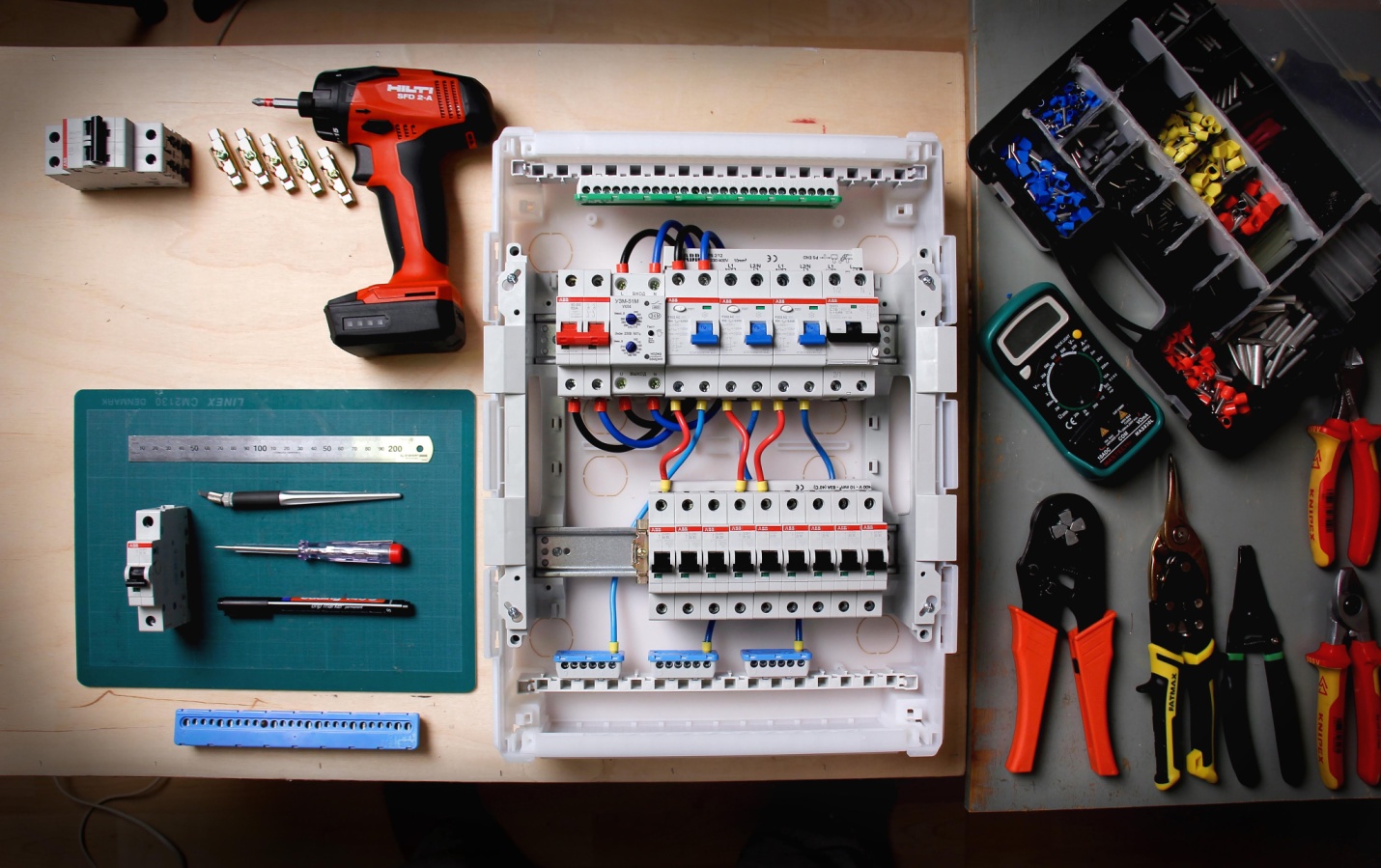
And now We will start with the fact that you have already installed the switchboard body and inserted the electrical cables into it. You should get something similar to what is shown in the picture on the left.
Step-by-step instructions for assembling and connecting an electrical panel.
- We comply!
- The first thing to do is install Din rails 35 mm in size, on which the , and busbars will be attached to each other, separately the neutral wires and .
The busbars, as you see in the picture below, are copper strips with holes for wires with bolts for clamping them. They are located on a dielectric plastic base that snaps onto the Din rail.
The latches, as can be seen in the picture, are arranged as follows: they snap into place themselves, and in order to remove the machine, you need to carefully pry up the latch with a spring inside using a flat screwdriver. The circuit breakers can be easily moved to the left or right if necessary. - After installing the rails, it is necessary, according to the electrical panel diagram you have chosen, to install the required number of circuit breakers, an RCD and 2 separate busbars with bolts on an insulating base. Grounding and neutral conductors will be connected to them accordingly. If there is free space in the protective cover, special plastic plugs are installed. Moreover, the input circuit breaker, which receives the cable that powers the entire electrical panel, is always placed first from the top left. For ease of connection, I advise you to insert the input cable above it from above.
- We connect the input machine, if it is two-pole, we connect phase and zero to it (designation N), if it is single-pole, we connect only the phase wire. If the shield is 380 volts, then you need to connect three phases to the input machine in the appropriate places. I recommend connecting the phases to the input circuit breaker from below, for convenience when later installing jumpers between the circuit breakers from above.
- We combine all machines and RCDs using specially designed copper bars in insulation.
 Or, as is more often done, we make jumpers from wires of sufficient cross-section and assemble an electrical panel diagram. We screw the blue neutral wire from the water cable onto the neutral bus directly, and when connecting RCDs and differential breakers, the zero is taken from the zero bus to each of them separately. And we connect the yellow-green wire to the ground bus. We also connect the body and door of the panel with a flexible metal copper wire, if they are made of metal, for the protective purpose of grounding.
 - We cut and connect outgoing electrical cables to the machines, according to the diagram below.

In the diagram, neutral conductors are highlighted in blue, phase conductors are highlighted in red, and ground conductors are highlighted in black and yellow. If a meter is installed in the switchboard, it must be connected according to the instructions on.
If you have installed differential circuit breakers or RCDs in the switchboard for sockets in your house, apartment, office, etc., the connection diagram will be slightly different.
In order not to make a mistake, always make zero jumpers in blue, and the phase jumpers are in a different color - red, for example. Grounding conductors are made of yellow-green wires. Always tighten the bolts on machines and tires well, check the connection is secure.
In private homes and offices, 380 Volt input is often used for the electrical panel, i.e. the electrical panel is supplied with power by a 4-wire or 5-wire cable (5 wires are grounding). An approximate common wiring diagram in the picture.
 3 different phases are connected to the input machine, which are then connected to the electric meter. From the metering device they go to a common machine, after which the phases diverge into single-phase machines for connecting equipment to a voltage of 220 Volts. Sometimes it is necessary to connect 380 Volt equipment; for these purposes, a 3-phase machine is used. Between opposite phases there will always be a voltage of 380 Volts, and between Zero and any phase = 220 V.
Be careful if you supply 2 phase or 380 V to household appliances instead Zero and Phase or 220 V - it will quickly fail.
The grounding conductor always passes by machines directly from the grounding bus. The zero is connected from another bus directly when the line is connected through a regular circuit breaker, but if the connection is made through an RCD or a differential circuit breaker, the zero goes through them to the connected line.
Attention! Installation and connection of an electrical panel is a complex and important stage of electrical work, which is carried out only after the voltage has been removed! If you doubt your capabilities, then it’s better to call a specialist!
As a result, after all the work is completed, your electrical panels will look like this.

All that remains is to screw on the protective cover and check your work by applying voltage to the electrical panel!
Related materials: