How to repair a household fan. Connecting a ceiling fan Chinese chandelier fan ceiling diagram
A fan, like any other electrical device, sometimes tends to break down; the stator winding in it most often burns out. But this is not at all a reason to send him into retirement. In this article, we will talk about the practice of repairing household fans.
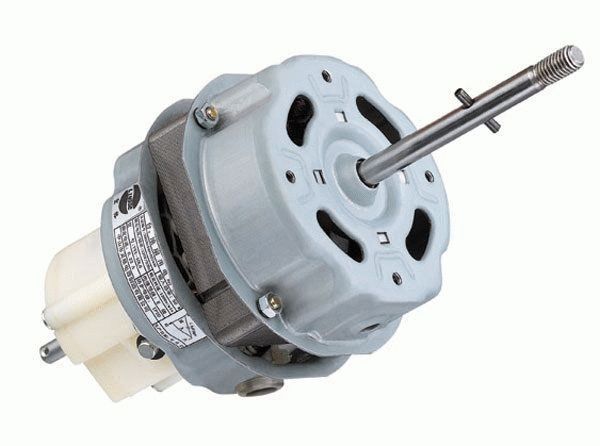
We begin the disassembly process by removing the fan cover; hidden under it is a small single-phase squirrel-cage rotor with a power of 20 watts. Let me remind you that the rotor is a moving part of an electric motor that rotates due to . Thereby driving the blades of our fan.
The stator is a static winding that is located on the steel core of the electric motor. The stator converts alternating current into a rotating magnetic field.
Upon external inspection, it is of course difficult to break any device if there are no obvious signs of damage that speak for themselves. In our example, we need to test the stator winding and power cord for integrity. The easiest way to do this is with a regular multimeter, which should be in the tool arsenal of any radio amateur. You can learn how to use a multimeter correctly.
After a series of measurements, it turned out that our power cord was in perfect order, and the stator winding of the household fan simply burned out. To repair it yourself, we will need to partially disassemble the engine. The stator winding can be removed quite easily using a regular screwdriver by driving it in with even blows in the places indicated by the arrows in the photo.

After successfully dismantling the stator winding, you can move on to mathematics, namely, calculating the number of turns for the motor stator winding.
For a simplified calculation, you can use the following algorithm as a basis:
The voltage in a normal alternating current network is 220 Volts, the engine power is 20 Watts, the cross-section of the core is 1.2 cm 2, the current passing through the coil will be 0.09 A. (based on the well-known formula I=P/U).
The cross-section of a typical wire can be calculated using the following formula:

If we convert the cross-sectional area of the wire from 0.03 mm 2 to the diameter of the wire, we end up with: d = 0.19 mm
I borrowed the winding wire from a coil of a magnetic starter with a diameter of 0.17 mm since I don’t know how to lay the required number of turns on the coil frame.
In the latter case: U is the mains voltage, S c is the cross-section of the core, B c is the magnetic permeability of iron (maximum 14,000 hectares).
As soon as we calculate the number of turns, we can start winding. It is difficult to wind so many turns around the core manually, so I recommend using a homemade one.
After the coil is made, it is necessary to impregnate it with a special impregnation varnish, otherwise the insulation of the wires in it may be damaged.
After the varnish has dried, you need to install the coil back. If, after assembly and testing, problems arise with the direction of rotation of the blades, then you only need to remove the rotor and install it on the other end of the core. Alternatively, you can pull out the stator coil again, rotate it 180 degrees and install it back.

In the figure above, short-circuited turns are marked with red arrows; the magnetic field rotating the blades, which acts on the rotor, will be concentrated on them.
In order to find the cause of the fan failure, it is necessary to disassemble it, as in the previous example. This is quite easy to do. First, we remove the protective grille, then take out the blades or impeller, which is usually secured with a special nut. Then you need to dismantle the other part of the protective grille and unscrew the cover screws.

I also recommend studying the typical circuit diagram of a floor fan. Typically, it uses an asynchronous electric motor with 8 windings (working and starting). To successfully start the engine, it is necessary to create a phase shift of 90 degrees. For this purpose, the circuit contains a capacitor. The circuit will work after pressing the power button, the indicator lamp should light up and the blades begin to rotate, the motor rotation speed depends on the connection diagram of the windings, using a switch.

First you need to check the serviceability of the network cable. Then execute to start the engine. It is also recommended to check the integrity of the contacts and wires. If a hum or noise is heard while the fan is operating, then you need to lubricate it with Litol thick lubricant.
Electric motor repair begins with lubrication of the bearings, usually after this the fan begins to work well. Machine oil can be used for lubrication.
A fairly typical malfunction is a break in one of the stator windings. To check, you can sharply rotate the blades in the direction of rotation clockwise. If the fan starts working, it means one of the windings has burned out.
The service life of the electric motor is reduced several times if you do not clean it of dust, or if you forget to lubricate the bearings or gearbox.
A fan is a device that creates air flow for cooling or circulation to eliminate unpleasant odors or remove harmful substances. Fans in everyday life are used as:
- desktop or floor devices to create comfortable conditions in hot weather;
- exhaust devices in kitchens, bathrooms and toilets;
- in computer technology for cooling power units: power supply, processor, hard drives, as well as for case ventilation;
- in welding inverters for cooling power electronic components.
Fans fail, but not in all cases you need to rush to a specialized workshop. The cost of repairing some products is sometimes comparable to the cost of purchasing new ones. Therefore, it is more advisable to try to repair them yourself.
DIY fan repair
Symptoms of a problem mechanical The fan parts are:
- strangers noises at work;
- speed reduction rotation, while the rotation of the shaft of the switched off device by hand occurs with force;
- full stop, in which rotation of the fan shaft by hand is impossible or requires significant effort.
TO electric malfunctions include:
- tripping of protective devices(circuit breakers) when the fan is turned on;
- smells burnt or overheated insulation during operation;
- speed reduction rotation when the shaft of the device is turned off;
- interruptions in operation when changing modes.
Mechanical faults that are not corrected in a timely manner progress and lead to electrical problems. Prolonged operation of the fan with jamming on the shaft leads to overheating and failure of the electric motor windings. A loose bearing allows the motor shaft to move in the radial direction, which leads to damage to the stator windings.
Therefore, if signs of a malfunction are detected, you must immediately begin to eliminate it.
Troubleshooting mechanical problems
Household fans do not have rolling bearings or the like, which are replaced in case of failure. They install plain bearings, the shaft rotates in bronze bushings. They are permanently pressed into the body. But even if you take them out of there, there will be nothing to replace them with. Therefore, it is necessary to lubricate such bearings in a timely manner. If they run dry for a while, the gap between the shaft and the bearing will increase. This will lead to axial runout of the shaft, resulting in extraneous noise, a decrease in speed and an increase in the rate of bearing wear. This is especially fatal for computer coolers.
Used for lubrication machine oil, but it’s better to use spindle. If you have a sewing machine at home, then oil for lubricating it is the best option for fan bearings. For lubrication, the fan must be disassembled to get to the bearings. For coolers and some exhaust fans, it is enough to peel off the protective film on one side.

Please note availability pollution bearing. In some cases, you will have to disassemble the assembly, clean it, and then reassemble and lubricate it. There is no need to apply a lot of lubricant: one or two drops are enough for the bearing to function normally. The rest will be splashed all over the body during the first launch. Drops of oil inside the case collect dust quite well.
If after lubrication there is still noise during operation or shaft beating, then the product will have to be thrown away. It is not possible to replace the plain bearing.
Troubleshooting the electrical part of the fan
When the fan stops completely, you need to check the serviceability power cord and switches operating mode. For this you will need a multimeter. The best method for testing the power cord is to measure the voltage at the fan input terminal block or where the cord connects to its internal components. Be careful when testing: do not touch live areas with your hands. After checking, immediately remove the plug from the outlet.
The serviceability of the switches is checked by measuring their resistance in the “on” position. They can fail if used frequently. It is best to immediately measure the voltage on the electric motor, but for this you need to know electrical diagram fan And also the principle of its operation and control of the rotation speed.
Speed adjustment is carried out by switching leads from the motor. In this case, one of its windings has a number of taps (tap taps), by switching which the number of turns on the stator changes. With this design, you need to measure before and after the switch to find out if it is working. If there is voltage and the motor does not rotate, you need to measure the resistance of its windings. If the device shows a break, it means that the engine is to blame for the malfunction.

Another element whose malfunction causes the fan to stop is phase shifting capacitor. In circuits where it is used, the electric motor has two windings. One of them is connected to the power supply directly, and the other is connected through a capacitor, which shifts the voltage across it in phase by 90 degrees.

If the capacitor fails, the winding either does not receive power or there is no phase shift. In both cases, the electric motor will not rotate. You can check the serviceability of the capacitor with a multimeter in resistance measurement mode. In this case, you need to select the largest measurement limit. Before connecting the device, the capacitor must be discharged by shorting its terminals together.
If, at the moment of touching the multimeter probes, readings appear briefly, and then it shows a “break”, then the capacitor is working. If its readings are zero or infinity and do not change, then the capacitor is faulty and requires replacement.
The operating voltage of the new capacitor should not be less than that of the one being replaced, and the capacitance should correspond to the original one. Its value is calculated in relation to the parameters of the electric motor winding; if it is changed, the phase shift angle will be greater or less than 90˚, and the fan will not start or will rotate more slowly.
Attention, do not mix up the winding terminals. Before disconnecting, mark the wires and sketch how they were connected. Additionally, take a photo of the assembly before disassembling.
If breaks in the motor windings are detected, the repair ends. You can try to find the break point or make sure that the winding has burned out (this is indicated by the darkening of the color of the insulation of its wires). But rewinding modern household devices is not economically feasible, and to carry it out at home you need to have professional wrapping skills. Therefore, devices with burnt-out electric motors can be thrown away without remorse.
How to properly connect a bathroom fan to a switch. How to connect a chandelier with a fan connection diagram
How to connect a chandelier with a fan: diagram
Differences in installation
During the hot season, a large ceiling fan performs better than other fan models in normalizing the microclimate in the room. The air flow from it covers a significant area. And even at low speeds, the effect is very pleasant for residents. The fact that the fan occupies a central place on the ceiling, which is usually used for a chandelier, does not cause problems, since in some models the functions of the fan and chandelier are combined.
But attaching a regular chandelier to the ceiling and a combined model are somewhat different. For an ordinary chandelier, a hook is sufficient, which is provided in any room. It is motionless and other than gravity, no other forces act on it. And when the impeller rotates, a torque arises. It is directed in the direction opposite to rotation. And this feature should be taken into account when hanging a ceiling fan of any design, especially when combined with a chandelier. In the absence of rigid fastening, axial movements will appear when the impeller rotates.
For high ceilings
A simple ceiling fan is not noticeable during these movements. But the movement of light bulbs in a chandelier with a fan will create an unpleasant lighting effect in the room. Light and especially shadows will begin to move. If the ceilings in the room are high, suspended ceilings are usually installed. The base of an ordinary chandelier is made at the level of the suspended ceiling and suspended on a chain or cable. These extension cords cannot be used for a chandelier with a fan. In this case, the best extension cord would be a metal pipe. Its diameter should be such that it fits onto the ceiling hook with two holes made near its end. These hook holes should be diametrically opposed.
The pipe is also convenient for placing wires inside it. Although the wires are connected as if to one device, they actually create two separately operating circuits. After all, during the day when the impeller rotates, lamp light is not needed. Therefore, to control lamps in the simplest circuit, you will need the same thing as for a chandelier. And the fan has its own separate circuit. It allows you to adjust the speed of the impeller. The connection diagram of the simplest model is shown in the image below. It has one lamp and one impeller rotation speed. Therefore, to control such a chandelier-fan, a switch with two keys is enough.
Variety of models
The number of lamps can be three, five, and sometimes more. The impeller speed can be divided into two or three stages and can even be adjusted smoothly. You can also smoothly regulate the light of lamps using dimmers. There are many models of such combined structures produced and it is unlikely that they can be standardized with just a few schemes. In order not to experience problems with installing the connection diagram for such a chandelier, when purchasing, you need to make sure that the accompanying documentation is available and everything is clearly stated in it regarding connecting the product to the electrical network.
If the connection diagram for a chandelier with a fan turns out to be too complicated to assemble it with your own hands, there will probably be specialists who will do everything necessary. When the selected model contains sensors for lighting control, or impeller rotation speed, there is a separate control unit, the possibility of programming is better to immediately resolve the issue upon purchase by calling a specialist to connect such a chandelier with a fan. You can not only fail to assemble a complex circuit with your own hands, but also damage something.
Podvi.ru
Wiring diagram for chandelier fan
What is the connection diagram for the fan adjacent to the chandelier
The connection plan for a fan with a chandelier is convenient. This device combines two devices in one, providing general illumination of the room and creating air movement in hot, windless weather, while saving on air conditioning. Most often, such fans are located in office buildings or small rented workshops, but they can also be located in everyday life. When purchasing such a fan, make sure that instructions are included with the kit. Previously, manufacturers added a section to it about the operation scheme, but due to frequent cases of copying, they stopped doing this.

But if you don’t go into details, the plan for connecting the ventilation inside the chandelier is quite simple. The illuminator has a built-in motor, which can be turned on either by a separate switch or switching combinations (restart), or together with the illuminator. The latter fan connection scheme is not recommended for use and is quite rare. It is not recommended due to the limitations of this scheme - when the lighting is turned on, the fan always works, which is unnecessary in cold weather. The recommended connection diagram is separate, when the operation of each function is regulated by its own switch.
A simple diagram for connecting a fan and chandelier
If you are choosing a fan with a chandelier for your home or home workshop, pay attention to the method of grounding the chandelier; in apartments it is TN-C. In office buildings or change houses, grounding methods may vary, so mistakes can be made. The required number of wires connected to the fan and panel depends on grounding. Attention, TT type grounding should under no circumstances come into contact with other electrical devices. If we talk about the TN-C system, then two cables, phase and neutral, will be pulled through the shield to the illuminator.

It will be necessary to connect zero and PE to the distributor via terminals. Attention: Observe safety precautions. When working with electrical appliances, it is necessary to turn off the power and check with a multimeter that there is no voltage on the wires. Only after this start working. Use terminals to connect the wires on the distributor; do not twist them under any circumstances.
In new houses it is already possible to use the TN-S grounding system. Its use is recommended and is a priority to ensure safety.
The use of TN-S implies the presence in the electrical wiring of a three-core copper cable, one of the cores of which serves to ground the circuit and is connected to the ground electrode in the distribution board. Accordingly, the device must have a grounding cable that connects to this core. The fan connection diagrams are different, but it is not possible to describe all of them. When purchasing, read the instructions and use the recommendations provided.
ampersite.ru
How to assemble a chandelier with a fan yourself? Simple recommendations with photos
Wiring diagram for a chandelier with a fan
Air circulation is very important, so the combination of a ceiling chandelier with a fan creates optimal working conditions. Such lighting devices can provide a flow of fresh air at any time of the year. Reviews of these models indicate that the rotation of its elements does not lower the temperature in the room.
There are different prices for lighting fixtures with a fan:
- in a low price category that can be bought inexpensively;
- at an average price, based on the family budget, select the appropriate quality;
- There are luxury models, their price is quite high.

If someone has wondered how to connect a chandelier with a fan independently in a three-phase network, then here you can find information on this issue.
Before you start connecting a chandelier with a fan, it is important to decide on its location so that the light falls evenly without disturbing the overall mood of the room. If you plan to connect it in place of the previous chandelier, then you can skip this point.

Next, determine the approximate weight of the chandelier and if you find that it weighs more than 13-15 kg, you need to install a beam that will help hold the chandelier. If you skip this step, you may damage the wires or the surface of the ceiling. In ordinary apartments it is unlikely that such a heavy chandelier will be found, so, most likely, you can do without installing an auxiliary beam.

Installation of distribution box
Before you start connecting the chandelier with a fan, you need to connect the junction box to the power cable. This must be done carefully and carefully, following all safety regulations.
The heart of the structure, that is, the electrical circuit, must be connected at a distance of a little more than 10 cm with the installed box; a supply of wires after connecting the cable is necessary in case of damage to the wires. Then you need to cover all the wires with a special cover. All wires must be insulated and the box must be tightly bolted.

There are already many reviews that are full of pleasant words in favor of such a design. This is not surprising, because buying such a lamp means giving yourself a soft, pleasant coolness along with gentle lighting. Air conditioners consume a large amount of electricity, which cannot be said about ceiling chandeliers-fans, which can be bought in a specialized store. For example, you can find a high-quality, sophisticated and functional model at Leroy Merlin.
Moscow stores have established themselves as reliable suppliers of high-quality designs, where you can easily find a wide variety of lighting fixtures and inexpensively. A photo of a chandelier with a fan will help you get to know the design better. In addition, the photos that are in this article can be an excellent assistant in choosing a chandelier suitable for combating stuffy and stagnant air in the room. The price of a chandelier with a fan is low compared to an air conditioner, and it is still more profitable to purchase such a design than an air conditioner and a chandelier separately.
ogodom.ru
How to connect a chandelier with a fan?
The first step is to turn off the plugs in order to de-energize the apartment; if possible, you can de-energize only the area where the chandelier will be installed. It would be a good idea to make sure that there is no voltage in the sockets of the sockets and on the wires; indicator screwdrivers are used for this. There should be three wires hanging from the ceiling, usually of different colors, you need to make sure that they are in good condition, then remove the insulation from the edges and straighten them on opposite sides of each other so that there is no possibility of them touching.
There are few differences in how to connect a chandelier with a fan from connecting a regular chandelier. The main thing is the ceiling box. For such a chandelier, you need to remove the standard ceiling box and install the one that comes with it. As a rule, it should be located on the ceiling rafters, which will securely hold the mechanism during rotation.
Now you need to determine which wires are “phase” and which, in turn, are “zero”. To do this, you need to turn on the voltage and check each of them with an indicator: in the case of “phase” it will light up, there should be two such wires. You can find out which wires are responsible for what on a chandelier by reading the installation instructions or looking at its diagram.
Then you need to turn off the voltage again and begin directly connecting the fan chandelier. To do this, you need to hang it on mounts from the ceiling and connect the wires according to the principle: phase to phase, zero to zero. At this stage, it is necessary to take into account one important point: the wiring in the apartment and on the chandelier can be made of different materials, so it is recommended to use connecting blocks. If you are sure that the wires are the same, you can connect them directly to each other.
It is necessary to adjust the height of the chandelier. The distance from the blades to the ceiling should not be less than 25 cm, however, the chandelier must be at a height of more than 2 meters above the floor level, otherwise a tall person may be injured. Before you put everything in place and assemble the tools, you need to turn on the voltage and check that everything is working correctly. If not, you need to look for where the error was made.
uznay-kak.ru
Fan-chandelier + photo
Not every family can afford to buy an air conditioner. Therefore, many people prefer to escape the sultry heat with the help of a more budget-friendly, but still effective device, which involves the presence of a fan in the design. It has many varieties and modifications, one of which is a chandelier with a fan, when using which you can not only cool down, but also get good lighting in any room.
Advantages

Previously, such devices were common in public canteens and large industrial premises. They were not produced for domestic use. But modern chandeliers are often equipped with a fan, making the ceiling lighting fixture multifunctional.
Among the advantages of chandelier fans are the following:


Design features and varieties
Design options using a lamp with a fan of various models and in various interiors are shown in the video:
Such devices are made from a variety of materials. These are plastic, glass, metal, wood, fabric inserts, etc. It will organically complement any interior, thanks to the variety of models offered.
You can use a ceiling fan for a variety of rooms, where its functions will become simply irreplaceable:
Many models of such ceiling fans are equipped with additional functions, for example, the ability to change the fan speed, as well as direction, reverse, remote control, and others. They are divided into universal ones, which can be used in almost any room, and household ones for home use.
In addition, due to the presence of lighting lamps, such a ceiling fan can have different types of lighting - colored or with halogen lamps.
Rules for selection and connection
When choosing a chandelier with a fan, you should definitely pay attention to such device parameters as:
- Fan blade diameter. They are selected depending on the height of the ceilings in the room, and the size of the blades themselves will affect the intensity of the airflow. If the ceiling height is less than 3 meters, then you should choose a ceiling fan with a blade diameter 2-2.5 times smaller than the area to be blown. In addition, the number of blades can vary from 1 to 10. The most common are luminaires with fans of 3-6 blades.
- Lighting parameters. In this case, the choice depends on the required level of lighting, which varies and changes with different numbers of lamps used and their power, as well as the size of the chandelier itself.

Connecting such a lamp with a fan is quite simple and will not cause any difficulties for a person familiar with the installation features of conventional chandeliers. This procedure is also facilitated by the connection diagram for a chandelier with a fan, which is usually included in the delivery package of the device.
For the work, you may need such accessories and tools as a construction knife, a screwdriver, a hammer drill (if the installation is on a concrete ceiling), dowels, and insulating tape.
Important! When installing such a device, care should be taken to soundproof the ceiling structure if it is made of plasterboard or tension systems, since vibrations created by the fan can make the use of such a lamp too noisy.

At the very first stage, a special ceiling hook is secured on which the entire structure will be supported. To do this, a dowel is driven into the ceiling, and a hook is attached to it. Three wires are used for connection - for the lamp, for ventilation and the zero phase.
Attention! If there is no experience in working with electrical communications, then it is better to entrust the installation of the device to professionals.
All wire connection points must be insulated. If a two-key switch is used for control, then the wires that come from it are stripped in turn and connected to the wires of the chandelier. In this case, one key turns on the lighting, and the second starts the fan.
Conclusion
By choosing a chandelier equipped with a fan for your room, you can get a multifunctional device that will not only provide the necessary degree of ventilation and coolness in the room, but will also be safe for health. It will also help save space and energy.
bouw.ru
Installing a chandelier with a fan
Since ancient times, people have dreamed of a device that creates a refreshing air flow. The first attempts to assemble a mechanical device capable of replacing and surpassing fans and fans were made back in the 16th century. In the 19th century, a device was invented whose rotating impeller moved air, bringing a feeling of coolness. The impeller was driven by water pressure, which was supplied through a pipe or hose. There was an attempt to use a steam engine for these purposes.
But the widespread distribution of such devices became possible only thanks to Thomas Edison: with the advent of the electric motor, the fan turned from an ineffective and bulky structure into an extremely useful device that creates comfortable conditions.
Since then, hundreds of models have been created that fully meet the various requirements.
The types used in everyday life include floor, table and ceiling fans. Next, we will look at issues related to installing the latest version.
One of the advantages of fans over split systems, in addition to cost-effectiveness, is ease of installation, which can be carried out without the involvement of specialists.
Installing a “ceiling light” is a little more complicated than installing a regular chandelier. Therefore, if you have minimal skills in performing electrical work, you can begin to secure and connect the device yourself.
Ceiling fans are distinguished by material of manufacture, diameter, number and size of blades, power, design and other parameters.
As a rule, all modern models are equipped with a lamp, and the lamp can work separately, the fan separately, or all together.
Ceiling height and room size are the most important criteria for selection. The distance between the floor and the blades should not be less than two meters and thirty centimeters - such standards have been adopted in order to prevent injury from rotating elements.
The traditional and most successful location of the device is the center of the room. If the room is small, the air flow created by one fan can provide a comfortable stay in it. In the case of a large area of the room, it may be necessary to install two or more “ceiling lamps”.
In some cases, it is necessary to draw a separate line from the shield to the installation site - if the laid wiring is not able to withstand the load from the engine and lamps turned on at the same time.
Before starting work, be sure to turn off the electricity. Then you should check the presence of a phase using an indicator - do not neglect this simple operation, especially since it does not require much time.
At the first stage, in addition to turning off the power supply, the tools are prepared. If you plan to install the fan in place of the old chandelier, then the next step is to dismantle the lighting fixture.
In most cases, it will also be necessary to replace the ceiling electrical box, which, as a rule, is designed to support the weight of the chandelier alone. Instead of the box, a special block is installed.
Next, you need to assemble the structure according to the manufacturer's instructions. Let us immediately clarify that in some models the blades and the lamp are screwed to the ceiling after the rod is secured. However, in most cases the fan is completely assembled at the bottom.
The blades should be screwed to the rod with the electric motor as securely as possible, the lamp should be fastened efficiently, but carefully so as not to damage the elements.
Wires for connection are pulled through the central hole.
Don't forget to screw in the lamp and cover it with the shade. Now the assembled device needs to be securely fixed to the ceiling.
- the device is fixed on a concrete base using dowels, mounting brackets and screws;
- if the ceilings are suspended or slatted, the fastening elements are placed on the main ceiling. This approach can be explained simply: the significant weight of the “ceiling”, reaching more than 20 kilograms, requires high-quality fastening. In addition, it is necessary to provide a gap between the decorative ceiling and the fasteners so that during engine operation vibration is not transmitted to the tensioned material of the decorative ceiling and does not create noise.
The wires of the fan and the wires of the ceiling electrical box must be connected in the sequence specified in the instructions, since manufacturers use different color markings.
The fan is usually mounted on a bracket, the terminal block of which is supplied with power from ground, and then the control unit is connected to the connectors.
After all connections are made, we proceed to the last phase: we fix the cover, which will give the entire structure aesthetics and completeness.
diskmag.ru
How to connect a fan to a switch

Surely you have encountered a situation in your life when there is an exhaust fan in the bathroom and it is turned on using a regular switch. Bathrooms in hotels, sanatoriums, boarding houses, and guest houses are often equipped this way. Maybe one of your acquaintances or friends has seen such a hood? By the way, this is a very good idea. And if your bathroom is not yet equipped with such equipment, we advise you to think about installing it. In this article we will talk about the advantages of the device and how to connect a bathroom fan to a switch.
Advantages
The bathroom is a room with high humidity. And excess moisture leads to the appearance of fungi and mold, various unpleasant insects such as centipedes and woodlice. If the bathroom is large, it can be equipped with various furniture (cabinets and shelves), and high humidity causes delamination of materials. Also in bathrooms there are metal structures (towel rails, towel and toilet paper holders), moisture accelerates their rusting.

Also, humidity is often accompanied by an unpleasant smell of dampness. And it’s even worse when the neighbors downstairs smoke in the bathroom, and the ventilation duct brings these odors to you.
Condensation also constantly collects on mirrors and walls, which can lead to premature destruction of the tiles.
Natural ventilation does not always cope with humidity and “odors” in the bathroom; sometimes it is further enhanced with the help of exhaust systems. One of these options is a fan.
Channel check
Before connecting the fan, you need to check the condition of the ventilation shaft.

Some people recommend this method by holding a sheet of thin paper to the vent. It should be attracted if the hood is good. But it’s more reliable to check with a flame, using matches or a candle. Light a candle and bring it to the hole, the flame should seem to stretch towards the channel. If this does not happen and the flame is even, it means that the ventilation duct is clogged and requires cleaning. To do this, you need to contact special housing and communal services.
Connection methods
Installing the future fan is half the battle; the main thing is to connect the power cable to it. If the bathroom has already been renovated well, this will be problematic. The ideal option would be to install the ventilation device at the stage of repair work, then the cable can be laid in the walls. Otherwise, you will have to come up with some kind of decorative design for it or plug it into an outlet.

Let's consider options for connecting a ventilation device:
- Diagram of parallel connection of a fan with a light bulb. In this case, both the fan and the lamp will operate from one switch. That is, the ventilation device will begin to rotate at the same time as the light comes on, and will be in operation as long as the light is on. The undoubted advantage is the simple and cheap implementation of such a scheme. However, there are many disadvantages. If the switch is turned off, it means the fan is not working, and this is not enough to ventilate the room. You will have to turn on and leave the light on for a while. On the other hand, the fan will always work when the light is on, and when a person takes water procedures, he does not need these drafts.
- Circuit from the switch. This method is definitely good, because it eliminates the stupid operation of the hood. That is, the device turns on and off only when needed. You can install a switch separately for the fan, or mount a 2-key switching device and power the lighting from one key, and the ventilation device from the second. This option will increase costs since more cable will be required. After all, the device is already connected directly from the switch with a separate line, and not parallel to the lighting.
- The latest fan models are already equipped with automation, in particular a timer. To connect such a device you will need a three-wire wire or cable; the third wire is connected through the light bulb and is a signal wire. There are two options for operating this fan. It can start simultaneously with the lighting turning on, and then turn off after a set time. Or vice versa, while the light is on, the engine does not start, but as soon as the light goes out, the fan starts working, and then it turns off after a certain period of time.

There are also fan models that are initially equipped with their own switch. It has the shape of a cord that comes out of the housing. Pulling this cord starts and turns off the device. But keep in mind that such models are completely inconvenient to maintain. Fans are usually installed near the ceiling, and this place is difficult to reach to reach the cord every time.
Fan installation
A two-core cable must be laid to the installation site of the ventilation device. Connecting a fan model with a timer to a one- or two-key switch is done with a three-wire wire (the third wire will be the signal wire).

Make grooves from the junction box to the ventilation hole. Remember that you can only groove with vertical or horizontal lines, there should be no inclined lines. Do not make grooves closer than 10 cm to the doorways. Place the cable in the groove made and secure it with alabaster or cement mortar. One end of the cable should be led out into the ventilation hole, the other into the junction box.
You can also run the cable in a corrugated pipe. Be sure to make sure that the corrugation is not located across the ventilation hole; it must be moved and secured to the side, otherwise it may obstruct the air flow.

The fan terminals are marked in English letters:
- “L” for connecting the phase conductor;
- “N” for connecting the neutral core;
- “T” - this letter is found in models with a timer; it indicates the location where the signal wire is connected.
In a cable, the cores are usually distinguished by color. The neutral conductor is made in blue, the phase conductor in brown or white. Connect the cable cores to the fan terminals accordingly. Check the reliability of the contact connection.
To install the fan in the ventilation duct, first remove the top cover with the mesh. On the bottom panel, to which the device itself is attached, there are four holes for self-tapping screws (usually they are included in the kit along with dowels). But if you already have tiles laid and you don’t want to drill them, use glue, such as silicone or liquid nails (anything can happen, the tile may crack or the glaze will chip off). Apply it to the back of the lid, insert the fan itself into the ventilation hatch, and press the lid tightly against the wall, hold for 1-2 minutes and release. Now replace the top decorative cover.
For more information on fan installation, watch this video:
The connection diagram for a fan with a timer is discussed in detail here:
Switch installation
Grooves from the distribution box must also be made to the installation site of the switch (in the case of walls made of plasterboard sheets, a corrugated pipe is used). It is necessary to lay a two-core wire in the grooves and fix it with a solution. The ends of the wire must be led out into the junction box and into the hole for the switch.

The switch is made of a working part and a protective cover with a button. A socket box must be installed in the hole. Now take the working mechanism; its contact part has two terminals for connecting wire cores. One terminal is an incoming contact; a phase conductor from the supply network is connected to it. The second terminal is the output contact; the phase from the fan will be connected to it. Make the necessary connections and check the reliability of the contact connections.
Fix the working mechanism in the socket box. Install the protective cover and put on the key.
If a switch with two keys is installed, then such a switching device has two output contacts, one of which must be connected to the fan, the second to the lighting device. Accordingly, one key starts the ventilation device, the second turns on the lighting in the bathroom.
Connecting wires

Now the following connections must be made in the junction box:
- Connect the neutral wire from the supply network to the zero wire of the fan.
- Connect the phase conductor from the supply network to the conductor that goes to the incoming contact of the switch.
- Connect the phase conductor of the fan to the conductor of the wire that comes from the output contact of the switch.
In the case of a two-key switch, the distribution box will additionally have the following connections:
- The neutral conductor from the supply network will still be connected to the neutral of the lamp.
- The phase core of the lamp must be connected to the wire core that comes from the second output contact of the switch.
As you can see, nothing complicated. Be sure to consider installing a fan in the bathroom. Nowadays they come up with a lot of fashionable electrical gadgets, but half of them are complete whims. But the ventilation of a room such as a bathroom is really not an unimportant issue. So this article is relevant and useful.
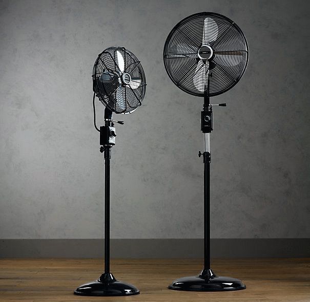
Let's look at repairing a floor fan with our own hands, using the example of a typical product from the Krasnodar plant. There is nothing complicated inside, but it is not easy to immediately describe the method of adjusting the rotation speed. The design is average. The relatively heavy body tramples on the weightless leg, sensing the slightest push, the product falls. The situation is aggravated by lying carpets. The four plastic supports scattered at the corners of the thin steel cross do not help. The stand is fragile, bends easily, and is supported by snot. Therefore, the first recommendation is not to deal with products that have mechanical instability, so as not to become infected with mental instability. Bork products are equipped with fall protection, but not products from the Krasnodar plant. However, the motor will not burn out in case of excess, there is protection...
Design of a typical floor fan
Do-it-yourself floor fan repair is on the agenda! You should start small: the simplest fans do not have a ground terminal. The device does not have a degree of electrical safety. The floor fan device includes a housing made of plastic. If water gets inside, expect a good shake. This type of floor fan should not be used near water. Starting with an aquarium with fish, ending with a flower vase. Particularly dangerous where small children live. If the thing falls, the child will guess to pour milk inside... Draw your own conclusions:
- the structure is unstable;
- the base breaks easily and bends;
- There is no protection against electric shock.
If a floor fan falls, there is a high probability that nothing will happen. Let's dive inside the structure. Let's leave aside for now the features of regulating the engine speed and buttons. Let's talk about the gearbox. The Krasnodar floor fan carries one asynchronous capacitor motor. The front side of the shaft is connected to the blades through a pin and a nut with a left-hand thread, the rear side goes to a gearbox formed by two gears, one double.

The shaft is equipped with a thread that engages the teeth of a large wheel as it rotates. The moment is transmitted to the small wheel, which drives the flywheel. The gear of the crank mechanism is the diameter of a hand, so the rotation is inferior to the speed of the original shaft of the asynchronous motor.
- The blades spin at full motor speed.
- The crank mechanism, thanks to the gearbox, moves more slowly.
Through the cardan transmission, the crank is hooked onto the leg, and the engine housing is mounted on the axle. When the shaft of an asynchronous motor rotates, the blades move smoothly in one direction or the other. However, you can stop the process. For a double gear, the roller is attached to the larger gear by two balls with a spring inserted into a through hole. If you pull the adjuster knob directly connected to the axle, the latch slides up. The connection between the gear and shaft is lost, and rotation stops. The mechanism provides fall protection: six grooves are cut into the inner mounting hole of the drive gear. Balls fit. There are six positions, the mutual transition is accompanied by a click, the axis rotates relative to the gear, the balls hit the walls, sliding into the grooves.
Clicking sounds are heard, there is a high probability that the floor fan has fallen. The drive is jammed, it works, clicking, a protective mechanism, protecting the motor from combustion.
We believe that the mode is unfavorable for a floor fan; if you do not turn off the device, the thermal fuse of the motor will certainly break. The gearbox is attached to the engine with three bolts and has a pair of lubrication holes through which the plastic gears can be lubricated. Refers to a drive rotating at the speed of an asynchronous motor.
Headache, how to fix a floor fan and assemble it. We see the situation: the relative position of the gearbox is incorrectly set, the legs through the gear, the head of the floor fan will move asymmetrically relative to the frontal plane. Can be annoying. Attach the gearbox, check the product by connecting power. Be careful not to get an electric shock, try to visually determine the correctness of the assembly.
Floor fan motor
Inside the fan there is an asynchronous motor with regulation of the shaft rotation speed by switching the windings. A capacitor is attached to the gearbox. The radio element is not a trigger element. We believe that it is not for nothing that the windings are fastened four in two rows, shifted relative to each other by an eighth of a turn. Field rotation uses voltage phase and 90 degree shift. The equipment is useless at this point, one winding of the asynchronous motor of the floor fan will burn out, and the motor will have to be replaced. It is not possible for a beginner to wind a complex product on his own.
Speed control is performed by switching the supply voltage to the appropriate wires by switching the buttons on the stand. One core goes from the cord from the outlet to the engine, and the position of the second is selected by the operator. Only one of the speeds is pressed at a time, which is ensured by mechanical methods of blocking parallel switching. Krasnodar products are pleased with the presence of backlighting: the top button ensures that the diode lights up. Allows you to avoid collisions with a floor fan in the dark. Indirectly indicates: the manufacturer is aware of the instability of the product.
The engine is made up of an insulated silumin rotor-drum, and the wiring of the coils is sealed. The structure remains unknown for obvious reasons; the question is meaningless. We believe that the probability of rotor failure is relatively small; the armature receives power from the stator. The structure is usually represented by a squirrel cage. A set of longitudinal conductors arranged in a circle, united by two rings at the ends. At both ends of the rotor there is an impeller that blows air over the stator coils. Allows the asynchronous motor to work harder. The Krasnodar floor fan has plastic impellers.
In case of uncertainty, test the wiring from the button (without disassembling the fan), examining the underlying fault. The resistance of the working winding is never zero, it is too high. The break is not difficult to guess. The starting winding rings from the contacts of the capacitor. The direction of rotation is determined by the relative position of the starting and main windings, therefore, if you mix them up, you will get the wrong result.
Of course, if at least one winding fails, the engine will not work. One phase is not enough to accelerate the rotor. Rotate the blades clockwise (with your hand withdrawn) to identify the presence of a characteristic malfunction. The floor fan will start working - one winding has burned out. It is incorrect to talk about starting and working coils; copper coils are identical. The motor is capacitor.
Floor Fan Motor Speed Control Method
Nothing is said about the speed control method, which is not surprising. In the model considered, four wires come to the coils, one supplies a plug. The other three enter the winding through fabric cambrics. What is inside is not known for certain. The choice is small; an asynchronous motor with an insulated rotor is controlled in two ways:
- Change in voltage amplitude.
- Switching windings with an unequal number of turns.
We don’t take inverter control into account; in this case there is simply no room for such a complex circuit. What remains is regulation of the voltage amplitude. Each wire has an unequal number of turns. If one speed (two) fails, the cambrics will have to be cut, therefore, the electrical circuit of the engine will become obvious. A diligent master will wind a new coil, a lazy one will take money from the client to buy a new engine (the old one will be used for non-ferrous metal).
The number of turns is indirectly determined through the resistance ratios between the terminals of each speed. The tester uses a constant voltage to measure the quantity, so the inductive part of the impedance is eliminated from consideration. The number of turns is directly proportional to the ohmic resistance of the winding section.
How to disassemble a floor fan
From what has been said, it is clear: there is nothing to break inside the floor fan. This is a motor and a capacitor. The rest falls on the mechanical part, the gearbox. If there is whistling or noise, try lubricating the gears. How to do this is clear from what has been said. There are a couple of holes in the gearbox housing for these purposes. Solid oil is suitable for plastic parts.
Repairing a floor fan yourself shouldn't be too difficult. Replace the motor with one of suitable weight and size. The main types of breakdowns concern the mechanical part; restoration is carried out using conventional (welding plastic with polyethylene) methods with skilled hands.
The control circuit for the chandelier with a fan is included with the product and should be included in the packaging. In the latest modifications of electrical products, the manufacturer does not provide an operation diagram, but shows a connection diagram. This way he protects his products from counterfeiting.
The simplest schematic diagram of a chandelier with a fan and its connection to the electrical network is shown in Figure 1.
The principle of operation is that when you turn on the power using a single-key switch, the electric light and fan are turned on simultaneously, i.e. The light is on and the fan is spinning.
A slightly complicated circuit diagram for connecting a chandelier is shown in Figure 2. 
Here the operating principle is separate, i.e. When you press one key of the switch, the light comes on, when you turn on the other, the fan runs. The fan operates regardless of the state of the lamp.
Connecting a chandelier with a fan to the electrical network comes down to the correct connection of the wires and this is a necessary condition for its operation. Depending on the type of grounding, a different number of wires come into the apartment and, accordingly, to the devices. For apartments of old construction, the TN-C grounding system is used, which is shown in Figure 3 (click to enlarge). 
The main thing in this system is that two wires come into the apartment - phase and neutral (PE and N conductors are combined). To connect a chandelier with a fan, you need to connect conductors N and PE on the terminal block of the distribution box according to Figure 4 (click to enlarge).


In this system, three wires come into the apartment - phase, neutral and ground. The PE conductor allows you to ground all equipment in the apartment and equalize the potentials. This system is modern and well protects people and electrical appliances in the house from the effects of electricity. Used to connect modern devices.
It is not possible to consider each of the chandelier circuits with a fan due to the huge number of manufacturers who expand the capabilities of the product. Chandeliers with a fan are found on sale and each of them has individual capabilities, control circuits and connections:
1. Chandelier with direct switching (Fig. 1);
2. With separate switching on of the chandelier and separate switching on of the fan (Fig. 2);
3. Fans with different blade rotation speed modes, with the ability to select a mode on a chandelier or multi-key switch.
4. Using optical sensors to turn on the fan and electric light, depending on the illumination of the room;
5. With a remote control unit, programmable settings: fan rotation speed, lamp brightness, depending on the light level, with the ability to set the on and off time for both lamps and the fan.
Chandeliers with a large number of lamps, with upper and lower light, have the same operating principle.
To properly turn on a chandelier with a fan, you must carefully read the connection diagram and follow the operating instructions or instructions for use.
Similar materials.